TM 5-3895-374-24-2
BULLETIN E-77
MODEL A-701 DIGITAL READOUT
INSTALLATION AND OPERATING INSTRUCTIONS
SPECIFICATIONS
Case
Standard 118 DIN
Accuracy
± 0.05% of reading
Conversion Rate
3 readings/sec.
Characters
0.6" LED, 31/2 digit
Input Impedance
1000 Meg OHM
Power Required
120 VAC
Power Consumption
6 watts
Integral Power Supply
24 VDC, 50mA
Weight
12 oz.
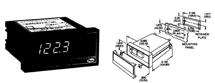
INSTALLATION
1) Case is standard 1/8 DIN size. To panel mount,
cut a 3.6" x 1.675" (92mm x 43mm) opening.
See figure A.
2) Remove front panel filter. Insert screwdriver
blade in slot at bottom to release catch and
gently pry outward.
3) Insert A-701 Digital Readout in panel opening
and install retainer plate from rear.
4) Slide mounting screws through reinforcing clips
and then through holes in readout case. Thread
into tapped holes in retainer plate and tighten
until unit is secure.
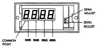
CALIBRATION PROCEDURE
Standard units are factory calibrated to read 00.0 with
4mA DC input and 100.0 with 20mA DC input, thus
indicating percentage of full range pressure or
temperature being sensed by the companion transmitter.
To adjust for other full range values from 500 to 1999
use the following procedure.
FIGURE A
1) Connect the readout in a current loop with an
accurate milliammeter and a current source.
2) With front panel filter removed, apply 4mA DC
loop current and adjust zero control for "00.0"
reading.
3) Apply 20mA DC loop current and adjust span
control for full span reading. If unable to reach
required reading it may be necessary to adjust
coarse span control located internally behind the
span and zero controls. Disconnect electrical
connector and slide internal assembly out to gain
access to this setting.
DECIMAL LOCATION
To change the location of the decimal point, install a
jumper from decimal common point to appropriate
terminal directly below the new position selected. See
figure B.
FIGURE B
(page 3-713)