TM 5-3895-374-24-2
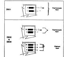
Type D931
Connect lead terminals 1 a 2 for 115 VAC or terminals 2
& 3 for 230 VAC (See Diagram 3).
Type D932
Connect supply voltage leads to terminals 1 & 2. (See
Diagram 4 and check designation label on controller for
correct voltage.)
Type D934
Connect supply voltage leads to terminals 1 & 2. (See
Diagram 5 and check designation label on controller
voltage.)
SENSOR (INPUT} CONNECTIONS
CAUTION: Do not run sensor leads through same
conduit or wireway with power or load leads.
THERMOCOUPLE TYPE J (D931) AND TYPES J & K
(D932 & D934)
•
Thermocouple
upscale
protection
for
open
thermocouple standard.
•
Always use the thermocouple extension wire and
connector matching the thermocouple calibration.
•
Thermocouple lead wire and extention wire are
color coded. The negative (-) lead is red. The
positive (+) lead is white for Type J and yellow for
Type K.
•
Always use .25 Faston female terminals for sensor
input terminal connections.
•
To compute total thermocouple error in degrees F,
select wire gauge and thermocouple calibration
and multiple total length of leadwire by value
shown in table below. Divide by 100 to compute
total setting and indicating error in °F.
Wire Gauge
20 (std)
12
14
16
18
24
J
.357
.054
.087
.137
.222
.878
K
.586
.091
.146
.230
.374
1.490
100 OHM PLATINUM RTD 3-WIRE D932 & D934
Always use equal lengths of extension wire. Always use
.25” Faston female terminals for sensor input terminal
connections.
Connect sensor (input) leads as follows:
Diagram 6
LOAD CONNECTIONS
WARNING: Power must not be applied direct
between common and heat (N.O.) or common and
cool (N.C.). Such connections place the power
directly
across
the
relay
contacts
and
will
permanently damage the controller. The heat and
cool terminals must be connected to he appropriate
loads before being connected to the load power line.
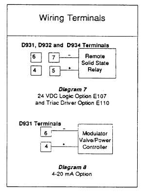
NOTE: Relay(s) are energized below set point(s).
Pilot light 1 is “on” below set point 1, and pilot light
2 is 'on' above set point 2. For standard units,
connect load lines per Diagram 3 (D931), Diagram 4
(D932) or Diagram 5 (D934). For units with options,
make wiring connections as shown in Diagrams 7, 8,
and 9.
CAUTION: Using Non-isolated 4-20 mA with Non-
isolated load can result in shock hazard.
NOTE: Maximum load impedance 750 OHM's.
Diagram 8
4-20 mA Option
(page 3-716)