TM 5-3895-374-24-2
INSTALLATION
1.
LOCATION: Select a location where the
temperature of the unit will be between 20F and
120F. Distance from the receiver is limited only
by total loop resistance.
See
"Electrical
Connections." The tubing feeding pressure to the
instrument can be run practically any length
required but long lengths will increase response
time slightly. Avoid surfaces with excessive
vibration.
2.
POSITION: The Model 604-0 must be mounted
and operated only in a vertical position due to its
sensitivity to gravitational forces. Higher range
models will perform properly at other angles, but
they must be spanned and zeroed in the position
in which they will be used. The minimum and
maximum ranges possible may shift depending
upon degree of tilt.
3.
PRESSURE CONNECTIONS: Two barbed
connectors are provided for use with 3/16" I.D.
vinyl or rubber tubing. Attach tubing from
positive pressure source to HI port. Leave LO
port vented. For negative (vacuum) pressure,
connect to LO port and leave HI port vented.
For differential pressures, connect the higher to
HI port and lower to LO port.
4.
MOUNTING: Attach the Series 604 transmitter
to a vertical surface using the 1"--#10 pan head
sheet metal screws provided. Mounting holes
are located in upper left and lower right comers
of case.
ELECTRICAL CONNECTIONS
CAUTION: DO NOT EXCEED SPECIFIED SUPPLY
VOLTAGE RATINGS. PERMANENT DAMAGE NOT
COVERED BY WARRANTY WILL RESULT. THIS
UNIT
IS
NOT
DESIGNED
FOR
AC
VOLTAGE
OPERATION.
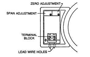
Electrical connections to the Series 604 transmitter are
made inside the enclosure on the left side of the unit.
Remove the cover, feed stripped and tinned leads
through the bottom holes and connect to terminal block
screws marked + and -. Refer to Figure A for locations
of terminal block, span and zero adjust potentiometers.
See Figure B for schematic diagram.
FIGURE A
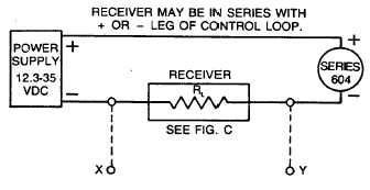
An external power supply delivering 12.3 to 35 VDC with
a minimum current capability of 20 milliamps must be
used to power the control loop in which the Series 604
transmitter is connected. Refer to Fig. B for connection
of the power supply, transmitter and receiver. The range
of appropriate receiver load resistances (R,) for the
power supply voltage available is given by the formula
and graph in Fig. C. Shielded two wire cable is
recommended for control loop wiring and the cable
shielding may be grounded if desired. Note also that the
receiver may be connected in either the negative or
positive side of the loop, whichever is most convenient.
Should polarity of the transmitter or receiver be
inadvertently reversed, the loop will not function properly
but no damage will be done to the transmitter.
FIGURE B
The Series 604 transmitters can be used with receivers
requiring 1-5 volt input rather than 4-20 mA. If the
receiver requires a 1-5 volt input, insert a 250 ohm, 1/2
watt resistor in series with the current loop but in parallel
with the receiver input. Referring to Figure B, RL
becomes the 250 ohm resistor and points X and Y are
connected to the receiver input, point Y being positive (+)
and point X negative (-) or ground. The resistor should
be connected at the panel end of the transmitter current
loop close to the receiver input to take advantage of the
immunity of the current loop to electrical noise pickup.
Most electronic component distributors stock a 249 r, /2
watt, i±% tolerance metal film resistor which is adequate
for this application.
(page 3-710)