TM 5-3895-374-24-2
CONNECTION TO THE A-701 DIGITAL READOUT
The Dwyer A-701 Digital Readout provides a 3 ½ digit
LED display of the relative or actual pressure being
sensed by the Series 604 Transmitter. The A-701
operates directly from standard AC line voltage. It is
suggested that you familiarize yourself in general with the
A-701 by reading the instruction bulletin supplied with the
readout. A printed circuit board edge connector is
supplied with the A-701 to facilitate the electrical
connections required. The standard A-701 is supplied to
read zero at 4 milliamps and 100.0 at 20 milliamps.
Thus, the standard digital display represents percentage
of full range pressure being sensed by the transmitter.
However, the A-701 can also be ranged in the field to
any engineering units required. To re4ange the display,
snap out the front panel and use a small screwdriver to
rotate the screw adjustment "F" at the lower left corner of
the LED circuit board until the intended reading at a loop
current of 20mA is obtained. With 4 mA loop current,
check the zero setting. If necessary, rotate the screw
adjustment "O" at the lower right comer of the LED circuit
board until the display reads zero. Since there is some
interaction between these controls, recheck and re-
adjust both settings until consistent operation is
achieved.
Refer to Figures E and F for connection of the
transmitter cable to the A-701 edge connector. Once
these connections have been made, connect the AC line
to the appropriate pins on the edge connector. The
installation is completed by the installation of the desired
decimal point selection jumper as indicated in Figure G.
Use care in identifying the appropriate edge connector
pins and solder each connection carefully. Use insulated
sleeving to cover the completed connections, particularly
the AC line connections. Note that the AC line power
required is minimal and lighter gage stranded wire is
recommended for the AC line connection. Be careful not
to bend unused lugs on the edge connector to avoid
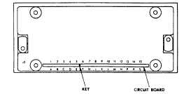
shorting adjacent connections. Observe the keyway in
the circuit board and on the edge connector when
installing the connector to the circuit board. Refer to the
A-701 instruction manual for mounting and dimension
information.
A-701 Pin Designations
NOTE: Pin designations for the edge connector are
the same as above when viewed from solder
lug side. Designations are also molded into
connector body.
FIGURE E
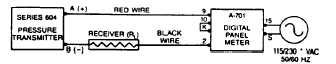
TABLE OF CONNECTIONS FROM A-701 TO
SERIES 604 TRANSMITTER
Pin 15: AC Line
115/230 VAC, 50-60 Hz
Pin S: AC Line
Pin 2: To negative terminal of Transmitter
Pin 9: To positive terminal of Transmitter
Pin 10 To Pin K: Jumper Wire
115 WC STANDARD, REFER TO FACTORY FOR 230 VAC.
FIGURE F
DECIMAL POINT SELECTION
No Jumper for 1999
Pin L to Pin N for 199.9
Pin M to Pin N for 19.99
Pin P to Pin N for 1.999
FIGURE G
MULTIPLE RECEIVER INSTALLATION
An advantage of the standard 4-20mA output signal
provided by the Series 604 Transmitter is that any number
of receivers can be connected in Series in the current loop.
Thus, an A-701 Digital Readout Accessory, an analog panel
meter, a chart recorder, process controlling equipment, (or
any combination of these devices) can be operated
simultaneously. It is only necessary that these devices all
be equipped with a standard 4-20mA input and that F per
polarity of the input connections be observed when insert
the device in the current loop. If any of the receiving
devices displays a negative or downscale reading, this
indicates that the signal input leads are reversed.
MAINTENANCE
Upon final installation of the Series 604 Transmitter and the
companion receiver, including the A-701 Digital Readout, no
routine maintenance is required. A periodic check of system
calibration is recommended. The Series 604 Differential
Pressure Transmitter is not field serviceable and should be
returned to the factory if service is required. The A-701
Digital Readout should be returned to the manufacturer if
service is required. Refer to the A-701 instruction sheet.
(page 3-712)