TM 5-3895-374-24-2
PART I. MOUNTING
WARNING: Always mount controller away from
shock, vibration, moisture and dust Locate where
there is sufficient space to, access to wiring
terminals on back of enclosure and where ambient
temperature remains between 32°F AND 130F
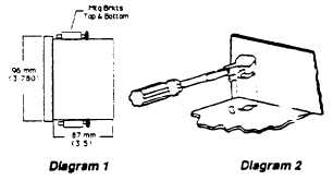
PANEL MOUNTING
PANEL CUTOUT: 92mm sq. (32.622)
Referring to Diagram 1, place enclosure, with face
oriented upright, into pane. Place mounting clamps into
slots at top and bottom of enclosure (Diagram 2). Using
a 3116 flat tip screwdriver, turn top damp left and bottom
right to lock unit into position. Tighten screws against
panel. Unit is now ready for wiring. If wiring space is
restricted, wire controller first, then mount.
PART II. WIRING
LINE VOLTAGE CONNECTIONS
WARNING: Wire controllers to comply with local and
national electrical codes. Use wire sizes #18, #16
and *14 only. Observe markings for the terminals;
incorrect wiring can damage the controller. Line
voltage power leads must be connected to proper
terminals, as listed below. Disconnect all power
before connecting wires to terminals.
IMPORTANT: Typical power for types D93 1. D932 and
D934 is 7VAC
(instrument).
External
fusing
is
recommended.
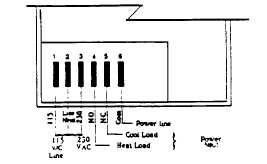
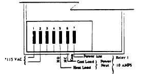
Connect line voltage power leads as follows:
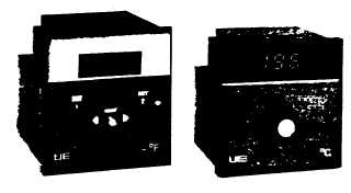
United Electric Controls Company
INSTALLATION AND MAINTENANCE
INSTRUCTIONS
TYPES D931, D932 & D934
SINGLE AND DUAL OUTPUT CONTROLLERS
Diagram 3
D931
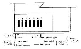
Diagram 4
D932
Relay 2 contacts are factory wired COM, N.O.
Diagram 5
D934
230 VAC If option E510 appears on designation lable
(page 3-715)