TM 5-3895-368-14&P
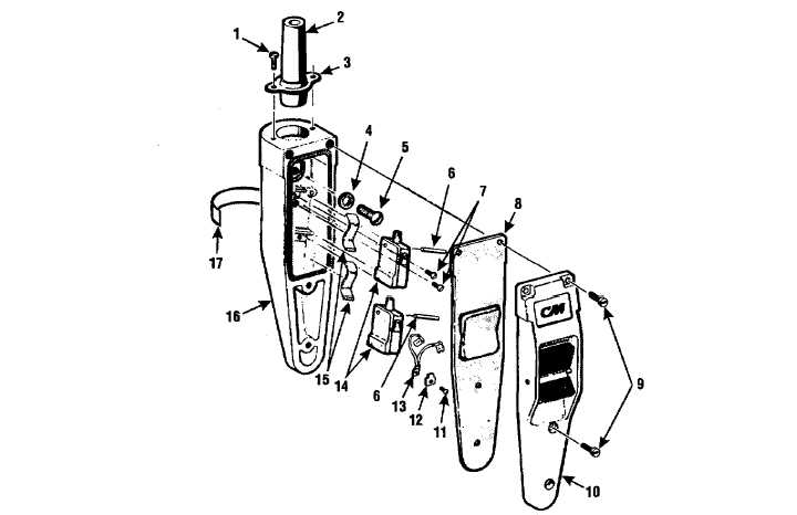
1. Screw (2)
2. Grommet
3. Retaining Ring
4. Washer
5. Screw
6. Pin
7. Screw (2)
8. Gasket
9. Screw (4)
10. Cover Assembly
11. Screw (1)
12. Terminal
13. Jumper Assembly
14. Switch (2)
15. Leaf Spring (2)
16. Case
17. Decal
Figure 4-6. Electric Hoist Assembly - Control Station
(b)
Clean exterior of coil (7), cable (20), power
cord (23), wire leads (24-32), contactor
assembly (36), switch (6, Figure 4-5),
capacitor
(17),
stator
assembly
(20),
grommet (2, Figure 4-6), gasket (8),
jumper assembly (13), and switch (14)
with a clean cloth dampened with water
and dry parts thoroughly.
(c)
Clean exterior of centrigugal (7, Figure
4-5) and rotor assembly (11) with cloth
dampened
in
an
approved
cleaning
solvent and dry thoroughly.
(d)
Clean all other parts except bearings with
an approved cleaning solvent and dry
thoroughly.
(2)
Inspect chain guides (22, Figure 4-4) for
wear, as evidenced by shiny areas, or
burring where chain enters the hoist.
(3)
Inspect each link of load chain (55) for
wear at saddles of links (contract area), as
evidenced by shiny areas. Inspect load
chain (55) for stretched condition (Figure
4-7), checking over several sections of the
chain. The diameter of new chain stock is
0.250 inch. The maximum allowable
length over 19 links for used chain is 14-
13/16 inches.
(4)
Inspect friction plates (2 and 4, Figure 4-3)
and brake discs (3) for evidence of
excessive wear. Replace parts which
have glassed or checked surfaces.
4-11