TM 5-3895-368-14&P
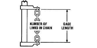
Figure 4-7. Chain Measurement Diagram.
(5)
Inspect electrical power cord (23), control
cable (20) and all wire leads for damaged
insulation.
(6)
Inspect contacts of contactor (36) and
switch (6, Figure 4-5) for burned or other
damaged condition.
(7)
Inspect all other parts for sign of wear,
cracks or other damage.
(8)
Replace any part found to be damaged in
any way.
h.
Assembly - Control Station (Figure 4-6).
(1)
Secure jumper assembly (13) and terminal
(12) to the case (16) with screw (11).
(2)
Seat leaf springs (15) in case (16) as
shown and secure switches (14) to case
with pins (6). Tighten screws (7) to secure
pins (6) in place.
(3)
Slide retaining ring (3) and grommet (2)
onto end of control cable (20, Figure 4-3).
Insert end of leads of the control cable into
the opening on end of case (16, Figure
4-6) and secure eye of control cable
restraint with screw (5) and flat washer (4).
Secure grommet (2) to case with two
screws (1) and retaining ring (3).
(4)
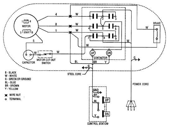
Refer to tags noted during disassembly
and wiring diagram (Figure 4-8) to aid in
making proper electrical connections.
(5)
Seat gasket (8, Figure 4-6) into cover
assembly (10) and secure the cover with
four screws (9).
Figure 4-8. Hoist Wiring Diagram.
4-12