TM 5-3895-368-14&P
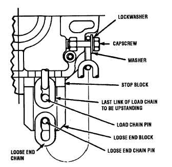
Figure 4-9. Chain Installation Diagram.
i.
Assembly - Gear and Hook Section (Figure 4-4).
(1)
If removed, install latch (3) and latch
spring (5), applying torque to the spring to
keep the latch closed. Secure latch and
spring with screw (4) and nut (6).
(2)
Install stem of upper hook assembly (2)
into adapter (8), and secure with nut (10)
and pin (11). Assemble screws (7) and
Nuts (9) to adapter loosely.
(3)
Install bearings (23 and 41) in bores of
motor housing (56) and. gear housing
(40), seating fully against shoulder.
(4)
Assemble chain (55) to liftwheel (21), with
last link on loose end side of hoist an
upstanding link and weld of up-standing
links to outside of liftwheel (see Figure
4-9). Assemble the chain guides (22,
Figure 4-4) to the liftwheel (21) and around
lift chain (55), seating the guides firmly
against each other with internal tab
engaging the chain slot of liftwheel.
(5)
Seat assembled chain (55), liftwheel (21),
and chain guides (22), with splined end of
liftwheel up, into motor housing (56),
engaging bearing (23). Chain guides must
engage the square boss of motor housing.
(6)
Install nut (20) in recess of motor housing
(56), with nylock side of nut toward
liftwheel (21).
(7)
Support assembled upper hook with nuts
(9) in slots of motor housing. Carefully
mate the motor housing (56) and gear
housing
(40),
aligning
liftwheel
with
bearing (23) in gear housing. Secure
housings with four screws (32). Ensure
that screws are tight.
(8)
Secure upper hook assembly (2) and
adapter (8). Torque the screws (7) to 30-
45 ft. lbs with 12-point socket and torque
wrench.
(9)
Assemble protector (38), with lettering
away from pinion, to intermediate pinion
(39) and secure with retaining ring (37).
(10)
Install bearing (36) onto shoulder of
intermediate pinion (39).
(11)
Install gear (33) onto liftwheel (21) and
secure with retaining ring (34).
(12)
Install shaft and pinion assembly (35),
meshing pinion teeth with gear of protector
(38).
(13)
Install the intermediate pinion (39) with
protector (38), carefully meshing pinion
teeth with gear (33).
(14)
If
removed,
install
plugs
(27)
and
expansion plug (26) in frame assembly
(25).
(15)
Install second bearing (36) into bore of
housing (25), seating in bore nearest the
brake studs.
(16)
Install flat washer (28), lockwasher (29),
and screw (30) in frame assembly (25).
(17)
Assemble new gasket (24) on mating
surface of gear housing (40) and carefully
guide frame assembly (25) over ends of
intermediate shaft (39) and shaft (35).
Seat frame assembly against gasket (24)
and secure with screws (31).
j.
Assembly - Motor End (Figure 4-5).
(1)
Install bearing (5) in cover (4), seating fully
against shoulder provided.
(2)
Position stationary switch (6) in cover (4)
and secure with two screws (9).
4-13