TM 5-3895-374-24-2
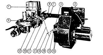
Figure 19
Typical Gas Burner with Low-High-Off or Low-High-Low Fuel/Air Control Mode (Model C-G)
MECHANICAL OPERATION: The Low-High-Off system uses a
Motorized Gas Valve (1) to control the Low-High-Off operation of
gas to the Firing Head (2), as well as movable Air Dampers (3) by
means of the mechanical Linkage (4). Gas flow control rate is
accomplished by adjustment of the Main Gas Pressure Regulator
(5) and by a Limiting Orifice (when installed) located in the Side
Orifice Tee fitting (7) at the inlet piping to the gas manifold. A
proven spark ignited gas pilot’ provides ignition for the main flame.
When the gas pilot’ has been proven by the flame detector
(scanner)’, the Motorized Gas Valve begins to open, allowing a
controlled fuel/lair mixture to the Firing Head for low fire light off -
and continues to open, increasing the fuel/air flow until the high fire
position has been reached. Firing head gas pressure are
measured at the 1/4“ plugged Gauge Test Port (8) in the Side
Orifice Tee. Refer to page 33, Table 10 for orifice sizing
information. The burner operates at high fire until the system load
demand is satisfied, at which time the Motorized Gas Valve closes
and the Air Dampers are returned to the light off position in
preparation for the next operating cycle. This depiction shows the
Linkage in the low fire start position. The Low-High-Low system is
identical to the Low-High-Off system except that - the Motorized
Gas Valve (1) has a Low Fire Operating Position Adjustment in
addition to the light off and high fire operating positions. (See
manufacturer's bulletin included with the burner.)
An additional temperature or pressure controller is added to the
system, which at a selected preset point will electrically switch the
Motorized Gas Valve and Air Dampers (3) to either the low fire or
the high fire position, as the system load demand requires.
Depending on system load conditions, the burner can alternate
indefinitely between the low and the high fire positions without
shutting down. When the system demand is satisfied, the
Motorized Gas Valve closes (normally the burner will be in the low
fire position at this time) and the Air Dampers are returned to the
light off position, in preparation for the next operating cycle. The
river Arm (10) connected to the Motorized Gas Valve will increase
the travel of the Air Damper Arm (13) as the Linkage Rod ball joint
(11) is moved away from the Gas Valve Crank Shaft (12). The
travel of the Air Damper Driven Arm will be increased as the
Linkage Rod ball joint (14) is moved toward the Air Damper Axle
Shaft (15). When adjusting linkage travel, make certain that the
driven arm Linkage Return Iron Weight (16) does not interfere with
the Linkage operation - and that all linkage components are free
from binding.
*Not shown in this depiction. See page 4, Fig. 2.
Note 1
Component operational
sequencing
will
vary with the specific Flame Safeguard
Control being used. Refer to the specific
Flame Safeguard Control bulletin supplied
with the burner for complete information.
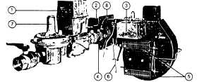
Figure 20
Typical Gas Burner with Full Modulation Fuel/Air Control Mode (Model C-G)
MECHANICAL OPERATION: This Full Modulation system uses a
Diaphragm (1) or Motorized Gas Valve to ensure opening and
positive closure of the gas source to the Firing Head (2). A
Modulating Motor (3) controls the positioning of a Butterfly Gas
Proportioning Valve (4) and movable Air Dampers (5) through
Mechanical Linkage (6). The gas flow control rate Is accomplished
through adjustment of the Main Gas Pressure Regulator (71 and
the Butterfly
(page 3-966)


