TM 5-3895-374-24-2
exchanger. The front plate must be protected from heat using high
temperature refractory on firebox side (as applicable).
To install the burner, a circular opening must be cut in the steel
front plate. Four (4) mounting bolts must be installed at proper
locations to match the mounting holes provided on the burner
mounting flange. (See dimensional drawings, page 5.) The burner
mounting flange must be securely attached to the front plate with
suitable gasket or non-asbestos, high temperature rope packing to
prevent any products of combustion from escaping from the
combustion chamber. The burner assembly should be supported
at the base of the housing to prevent undue strain on the front
plate. (A mounting pedestal is furnished for this purpose.)
Type C burners are furnished with a lifting lug for ease of handling
and mounting.
Combustion Chamber - General
Combustion chambers shall be provided as recommended in
“Chamber Dimension Charts,” and should be constructed of high
temperature refractories, in the form of firebrick or rammed plastic
refractory, backed by suitable heat insulating material. Certain
types of heat exchangers, such as warm air furnaces, some hot oil
heaters, wet base steel and cast iron packaged firebox boilers and
Scotch marine boilers, use the combustion chamber to transfer
heat, and therefore do not require refractory or other insulation. If
in doubt, consult the heat exchanger equipment manufacturer.
Where boilers are of the mud-leg type, refractory should extend 6”
to 8” above the bottom of mud-leg.
All possible points of air infiltration or ex-filtration must be sealed.
If the unit is to be fired under positive combustion chamber
conditions, extreme care must be taken to ensure that a 100% seal
is maintained. The Type C burner is designed to provide all the air
required for complete and efficient combustion. Entry or loss of air
from sources other than the firing unit will decrease its overall
combustion and operational efficiency. See page 12, Figs. 13
through 16 and Table 7 for additional information.
Figure 13
Conventional Firebox Boiler
Figure 14
Figure 15
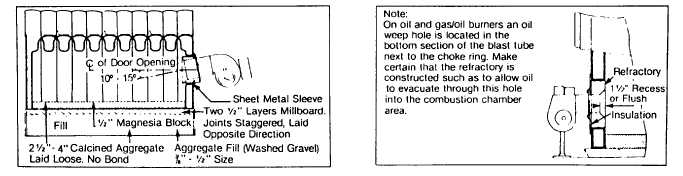
Typical Firedoor Installation -
Cast Iron Boiler Packaged Firebox Boiler
Figure 16
Scotch Marine Boilers
Scotch Marine Boiler Minimum Furnace Tube Inside Dimensions
BHP Min Inside Dimension
BHP Min Inside Dimension
BHP Min Inside Dimension
20
14”
80
20”
200
28”
30
16”
100
22”
250
34”
40
16
125
22”
300
34”
60
19
150 -
24”.
350
38”
Note:
The above minimum dimensions are recommended. If boiler dimensions are less, consult with
factory. All burners set through refractory with sleeve to allow field removal. Unlined space
between sleeve and burner blast tube closed with non-asbestos high temp rope or KA-O-Wool.
(page 3 - 964)