TM 5-3895-374-24-2
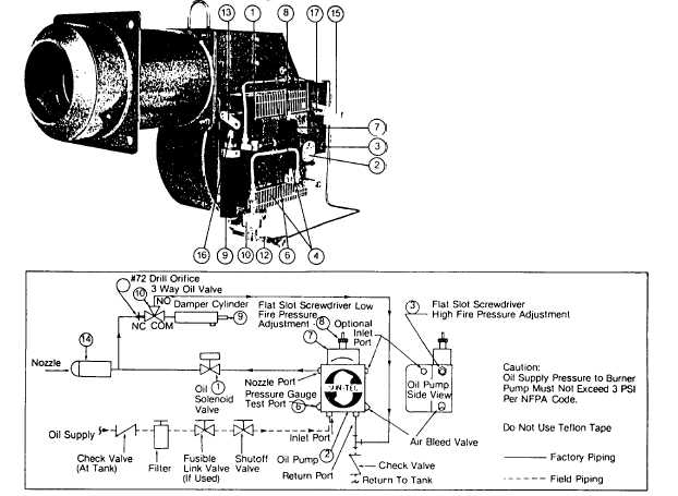
Figure 24
Typical Oil Burner with Low-High-Off or Low-High-Low Fuel/Air Control Mode Using a Two-Step Oil Pump. (Model C-0)
MECHANICAL OPERATION: This Low-High-Off system uses a
Two-Step Oil Pump with a simplex Oil Nozzle (14) in conjunction
with movable Air Dampers (4) to provide a low fire start and a high
fire run sequence. A direct spark oil ignition system will normally
be supplied, but certain insurance company codes could require a
spark ignited gas pilot to provide ignition for the main oil flame.
Nozzle flow rate pressure is taken at the 118” Plugged Pump
Pressure Gauge Port (6). The low fire oil rate is set by adjusting
the Oil Pump Low Pressure Regulator (8). The high fire oil flow
rate is set by adjusting the Oil Pump High Pressure Regulator (3).
For both high and low fires turn the adjustment screws clockwise
to increase the pressure and counterclockwise to decrease the
pressure to the Nozzle. Approximate low fire oil pressures are 100
to 125 psig and high fire, 200 to 300 psig. Both settings will vary
depending upon the specific nozzle size selected and job
conditions. See pages 30-31, Tables 8 & 9 for specific nozzle
pressures and flow rates. At light off the Main Oil Solenoid Valve
(1) is energized, allowing fuel to the Nozzle. A normally open
pump mounted Oil Solenoid Valve (7) allows a controlled flow of oil
to the Nozzle in accordance with the pressure setting of the pump
low fire adjustment. When the low fire flame is proven by the
flame detector*, the pump mounted, normally open Solenoid Valve
is energized (closes), putting full high fire pump pressure on the
nozzle. Simultaneously, the Three-Way
Solenoid Valve (10) is energized, allowing oil into the Hydraulic Oil
Cylinder (9) which mechanically drives the Air Damper Arm (13) to
the high fire open position. The burner operates at full high fire
until the system demand is satisfied. This depiction shows the Air
Dampers and the Hydraulic Cylinder at the low fire light off
position.
The Low-High-Low systems are identical to the Low-High-Off
system, except that an additional temperature or pressure
controller is added to the system. At a selected preset point, it will
electrically switch the Oil Valves and Air Damper components to
place the firing rate either in the low or the high fire run position.
When the burner is running at high fire and the controller calls for
low fire, the normally open pump mounted Solenoid Valve (7)
(which is closed at high fire) is de-energized (opens), reducing
nozzle pressure to the low fire rate. Simultaneously, the Three-
Way Solenoid Valve (10) is de-energized, allowing oil to flow out of
the Hydraulic Cylinder back to the Pump (2) and driving the Air
Dampers (4) to the low fire position. Depending on load
conditions, the burner can alternate indefinitely between the low
and the high fire positions, without shutting down. When system
demand is satisfied all fuel valves are de-energized and the Air
Dampers are placed in the light off position for the next start up.
The Air Damper position for low fire run and light off position are
one and the same in this system. The opening distance of
(page 3-970)