TM 5-3895-374-24-2
Table 6
Oil Pump Suction Capacity and Filter Selection Chart
Gas/Oil Model
Oil Model
GPH
Power Flame
Alternate
Suction
Oil Filter
Oil Filter
Capacity
Model
C1-GO-10
70(1)
7031160
73410 (Fulflo FB-6)
C1-GO-12
C1-0 and Cl-OS
70(1)
7031160
73410 (Fulflo FB-6)
C2-GO-15
C2-OA and C2-OAS
70(2)
7031160 .
73410 (Fulflo FB-6)
C2-GO-20A
C2-OB and C2-OBS
70
70101-100
73410 (Fulflo FB-6)
C2-GO-20B
C2.B and C2-OBS
70
70101-100
73410 (Fulflo FB-6)
C3.GO-20
C30
105
70101-100
73410 (Fulflo FB.6)
C3-GO25
C3-O0
105
70101-100
73420 (Fulflo FB.10)
C3-GO-25B
C3-OB
135
70101-100
73420 (Fulflo FB-10)
C4GO25
C4-OA
135
701014100
73420 (Fulflo FB-10)
C4GO-30
C4-OB
135
70101-100
73420 (Fulflo FB-10)
G5-GO-30 & 30B
C5-O & OB
250
70101-100
73290 (#72 1" Hayward
C6-GO-30
C6-O
250
70101.100
with 100 mesh basket)
1. The standard pump normally supplied is a19 GPH for
On-Off or Modulating and 40 GPH for fixed air low
fire start, Low-High Low operation. Optional pumps
are available which, depending on model specified,
could be as high as 70 GPH. Refer to information
shipped with the burner and/or consult the factory for
specifics.
It is very important to properly size the oil suction line and
oil filter to provide fuel flow to the burner without
exceeding 10” suction pressure (vacuum) at the oil pump
suction port.
2. The standard pump normally supplied is 40 GPH for
Low-High-Off and Low-High-Low and 70 GPH for On-
Off and Modulating operation. Optional pumps are
available for Low-High-Off and Low-High-Low which
could be as high as 70 GPH. Refer to information
shipped with the burner and/or consult the factory for
specifics.
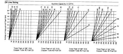
The method to properly size copper tubing is outlined
below (Fig. 10). Consult Power Flame Customer
Services Department for sizing assistance regarding iron
pipe.
1. Check oil pump “GPH Suction Capacity” shown in
Table 6.
2. Measure total tube length (horizontal and vertical)
from the end of the line in the tank, to the connection
at the oil pump.
3. Choose the appropriate graph above based on the
tubing size. Read up from horizontal line “total feet
of copper tube” to “Suction Capacity” in GPH.
4. Read left to the vertical line “Inches of Vacuum at
Fuel-unit”. (This is the vacuum required to draw oil
through the length of tubing selected.)
5.
If installation has lift (“Lift” is defined as the vertical
distance the fuel unit is above the top of the tank)
add “1” of vacuum for every foot of lift.
6.
Add the vacuum determined from items 4 and 5
together to determine total inches of vacuum.
7.
If total is over 10”, move to next larger tubing size
chart and re-calculate total inches of vacuum.
8.
The instructions above doe not allow for any added
restrictions, such as line filter, elbows, sharp bends,
check valves, etc. Suction line vacuum values for
such components vary from one manufacturer to
another.
A Rule of thumb to determine total vacuum for
suction line sizing is to add 10% to vacuum
determined from Fig. 10 calculations.
9.
It is always safe to size the return line from pump to
tank at the size as the selected suction line.
(page 3-962)