TM 5-3895-374-24-2
Table 7
Suggested Firebox Boiler Combustion Chamber Dimensions
Oil
(C)
Gas
Input
Minimum
Model
Input
GPH
(W)
(L)
Tube
Number
MBTU Hr.
#1, #2 Oil
Width
Length
Height
C1-GO-10
300
2.5
13
17
3
C1-G-10
500
3.5
16
22
3
C1-0
800
6
19
25
3
980
7
20
28
3
C1-GO-12
700
5
13
17
3
C1-G-12
900
6.5
20
28
3
C1-0
1150
8
22
30
3
1260
9
23
33
3
C2-GO-15
1000
7
21
29
5
C2-G-15
1300
9
23
33
5
C2-OA
1600
13
25
38
5
2100
15
27
42
5
C2-GO-20
1500
11
25
38
5
C2G-20
2000
14
27
42
5
C2-OB
2500
18
29
46
5
2900
22
30
48
5
Oil
(C)
Gas
Input
Minimum
Model
Input
GPH
(W)
(L)
Tube
Number
MBTU Hr.
#1, #2 Oil
Width
Length
Height
C3-GO
2400
17
27
44
5
CG-3
3300
24
33
53
6
C3-O
4200
30
37
62
8
5250
37.5
40
68
9
C4-GO-30
4000
29
35
58
8
C4-GO-30
5500
40
42
70
9
C4-O
7000
50
45
76
12
7840
56
48
79
13
C5-GO-30
6000
43
43
72
10
C5-G-30
7500
53
48
79
13
C5-O
9000
65
50
80
13
10500
75
54
84
15
C6-GO-30
8000
57
48
79
13
C6-G-30
10500
75
54
84
15
C6-0
12500
89
60
90
17
14215
101.5
64
95
18
Note:
These dimensions are to serve as a guide
only,
and
may
be
modified
providing
approximate area is maintained.
3. MECHANICAL OPERATION OF FUEL/AIR CONTROL MODES
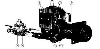
Figure 18
Typical Gas Burner with On-Off Fuel/Air Control Mode (Model CR-G)
MECHANICAL OPERATION: This system uses a combination
Diaphragm Gas Valve and Integral Pressure Regulator (1) to
control the on-off operation of gas to the Firing Head (2). A proven
spark ignited gas pilot provides ignition for the main flame. Gas
flow control rate is accomplished by adjustment of the main gas
pressure regulator and by a Limiting Orifice (a limiting orifice is
used wen the gas flow rate - BTU input - through the gas train
components is higher than desired), located in the Side Orifice Tee
fitting (5) at the inlet to the gas manifold. The Air Dampers (6) are
adjusted and locked in place with the Air Damper Arms (7) for a
fixed firing rate. When the gas pilot’ has been proven by the flame
detector’, the Diaphragm Gas Valve will open slowly, allowing gas
to the Firing Head. Firing head gas
pressures are measured at the 1/4 Plugged Gauge Test Port (8) in
the Side Orifice Tee. Refer to page 33, Table 10 for orifice sizing
information. See page 32, Fig. 33 for side orifice detail.
*Not shown in this depiction. See page 3, Fig. 1.
Note 1
Component operational
sequencing
will
vary with the specific Flame Safeguard
Control being used. Refer to the specific
Flame Safeguard Control bulletin supplied
with the burner for complete information.
Note 2
Optional On/Off systems may be supplied
using a separate gas pressure regulator and
separate diaphragm or motorized gas valve
in place of the combination regulator/valve
unit depicted. Other components would
remain as described.
(page 3 - 965)