TM 5-3895-374-24-2
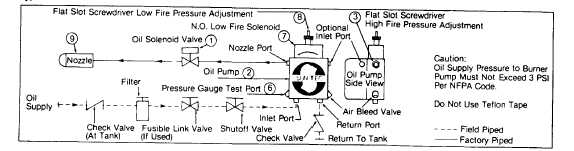
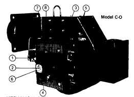
Figure 22
Typical Oil Burner with Fixed Air Low Fire Start Fuel/Air Control Mode
MECHANICAL OPERATION: The fixed air low fire start system
uses a two-step, two-stage Oil Pump (2) with a Simplex Oil Nozzle
(9). A direct spark oil ignition system will normally be supplied, but
certain insurance company codes could require a spark ignited gas
pilot* to provide ignition for the main oil flame. The nozzle flow
rate pressures are taken at the Plugged Pump Nozzle Pressure
Gauge Port (6). The low fire oil flow rate is set by adjusting the Oil
Pump Low Pressure Regulator (8). The high fire oil flow rate is set
by adjusting the Oil Pump High Pressure Regulator (3). For both
high and low fires, turn the adjustment screws clockwise to
increase the pressure and counterclockwise to decrease the
pressure to the Nozzle. Approximate low fire pressures are 150 to
225 psig and high fire, 200 to 300 psig. The Air Dampers (4) are
adjusted and locked in place with the Air Damper Arms (5) for
correct combustion values at the high fire rate. At light off, the
Main Oil Solenoid Valve (1) is energized, allowing fuel to flow to
the Nozzle. The normally open Low Fire Solenoid Valve (7) allows
a reduced amount of oil to the Nozzle for low fire start. When the
flame is proven by the flame detector’, the low fire solenoid valve
closes, providing full high fire pressure to the Oil Nozzle. The
burner operates at the high fire position until the system load
demand is satisfied. Refer to page 31, Table 9 for specific nozzle
pressures and firing rates. See page 11, Fig. 11 and the pump
manufacturer’s bulletin supplied with the burner for additional
information.
* Not shown in this depiction. See page 3, Fig. 1.
Note 1
The system depicted uses a two-step
Suntec oil pump. If a pump that does not
have the integral two-step function has been
specified and supplied, it will be provided
with a N.C. nozzle bypass oil solenoid valve
and a separate adjustable low fire relief
valve. Refer to the oil piping diagram and
the
oil
pump
manufacturer’s
bulletin
supplied with the burner for specifics on
your system.
Note 2
Component operational
sequencing
will
vary with the specific Flame Safeguard
Control being used. Refer to the specific
Flame Safeguard Control bulletin supplied
with the burner for complete information.
Figure 23
Typical Oil Burner with Low-High-Off or Low-High-Low Fuel/Air Control Mode Using Webster 22R Oil Pump
(page 3-968)