TM 5-3895-374-24-2
The standard inlet air filter is suitable only for normal
industrial applications. Should the compressor be located in
an area where the atmosphere contains a heavy concentration
of dust and dirt, an air filter utilizing a specially designed,
heavy duty (4 micron) element should be used.
All applications of this nature should be referred to
the nearest Ingersoll-Rand sales office or distributor.
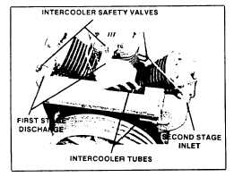
INTERCOOLER
This compressor is equipped with an intercooler
between the first-stage and the second-stage See Figure 4-2.
The purpose of the intercooler is to remove most of the heat of
the first-stage compression from the air before It enters the
second-stage, thus improving efficiency and decreasing the
final discharge air temperature.
The intercooler consists of one or more finned tubes
connecting the discharge of the first-stage to the inlet of the
second stage.
The compressed air flows through these tubes
and its heat is transferred to the cooling fins, where the air
from the belt wheel fan passing over the fins dissipates the
heat to atmosphere.
Never permit the air flow to these tubes to become
obstructed, and clean the surfaces of the tubes whenever
deposits of oil, dirt or grease are observed. Use a non-
flammable safety solvent for cleaning purposes. During
regular overhaul periods, the tubes should be removed from
their headers and inspected internally. If the interior of the
tubes requires cleaning, cap one end and fill it with a non-
flammable safety solvent to help loosen internal deposits of oil,
dirt and carbon. Always flush the tubes with warm water and
permit them to dry thoroughly before replacing.
Figure 4-2.Typical Intercooler Tubes and Safety Valves.
SAFETY VALVE
Safety Valves are designed to protect against
damage from over pressure. This compressor will be
furnished with the following ASME approved safety valves.
1.
Intercooler Safety Valve-The Model 7100 will be
supplied with one 80 PSIG (5.6 kg/cm2) safety valve installed
in the intercooler, and the Model 3000 will be supplied with two
80 PSIG safety valves installed in the intercooler. See Figure
4-2.
2.
Receiver Safety Valve-Receiver mounted units will be
supplied with a 200 PSIG (14.1 kg/cm2) safety valve installed
in the receiver.
3.
Discharge Safety Valve-On models that are supplied
with an aftercooler or tank silencer a 325 PSIG (22.8 kg/cm2)
safety valve is installed between the compressor discharge
and the aftercooler/silencer.
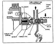
STARTING UNLOADING SYSTEM
OPERATION OF STARTING UNLOADING SYSTEM - The
purpose of the system is to relieve cylinder pressure
when the compressor stops permitting it to start against a light
load; increasing the life of the driver and belts and also
reducing the possibility of tripping the overload relay. The
system operates in the following manner:
As shown in Figure 4-3, the centrifugal unloader is
attached to
Figure 4-3.Position of weight and thrust pin when compressor
is stopped.
This machine contains high pressure
air. Can cause injury or death from
flying parts.
Do
not
remove
change
or
make
substitutions for the safety valves.
They should be replaced
only
by
genuine I-R replacement parts.
.
This machine contains high pressure
air. Can cause injury or death from
flying parts.
Do
not
remove
change
or
make
substitutions for the safety valves.
They should be replaced
only
by
genuine I-R replacement parts.
If a separate or detached air receiver is
used, a properly rated ASME approved
safety valve must be installed in the
receiver.
This machine contains high pressure
air. Can cause injury or death from
flying parts.
Do
not
remove
change
or
make
substitutions for the safety valves.
They should be replaced
only
by
genuine I-R replacement parts.
If an aftercooler or any other restriction
is added to the compressor discharge,
an ASME approved safety valve must
be installed between the compressor
discharge and the restriction.
WARNING
page 3-837