TM 5-3895-374-24-2
SECTION III
REGULATION
TYPES OF REGULATION
(See Wiring Diagrams on page 24)
The Model 7100 and 3000 Package Compressors are
supplied with Dual Control Regulation, and the Model 7100
and 3000 Bare Compressors are supplied with Constant
Speed Control Regulation.
Dual Control is accomplished by a combination of
Auto-Star t And-Stop Control Regulation which consists of a
pressure switch that makes or breaks the electrical contacts to
the motor at a predetermined pressure setting, and Constant
Speed Control Regulation which unloads the compressor at a
predetermined pressure setting while the motor continues to
run
AUTOMATIC START AND STOP CONTROL
This type of regulation is used when the demand for
air is small or intermittent, but where pressure must be
continuously maintained.
Automatic Start and Stop Control is obtained by
means of a pressure switch which makes or breaks an
electrical circuit, starting and stopping the driving motor,
thereby maintaining the air receiver pressure within definite
limits.The pressure switch is piped to the receiver and is
actuated by changes in air receiver pressure.
Automatic Start and Stop should only be used when
motor starts no more than 6-8 times per hour.
CONSTANT SPEED CONTROL
This type of regulation is used when the demand for
air is practically constant at the capacity of the compressor.
Constant Speed Control is obtained by means of an
auxiliary valve that controls the operation of the Inlet
Unloaders, thereby loading and unloading the compressor in
accordance with air receiver pressure. This action maintains
receiver pressure within definite limits while the compressor
continues to operate.
The auxiliary valve is piped directly to the receiver
(See Figure 3-4)
When receiver pressure reaches the pre-set unload
pressure the auxiliary valve actuates and compressed air from
the receiver activates the inlet unloader piston.
This
compressed air forces the unloader piston against the intake
air seat in the unloader which blocks the flow of intake air,
through the filter/silencer.
When receiver pressure falls to the pre-set load
pressure, the auxiliary valve closes, shutting off pressure to
the unloader vacuum within the inlet port retracts the piston.
The air inlet opens and the compressor reloads.
DUAL CONTROL
Dual Control is accomplished by adjusting the lockout knob on
the top of the auxiliary valve. See Figure 3-3 For
constant speed operation, turn the knob counterclockwise until
fully open. This adjustment will allow the valve to function.
Turning the knob clockwise locks-out operation of the auxiliary
valve. Note-the pressure gauge reading at which the
compressor cuts-out and re-establish this point if necessary.
For proper dual control operation, the cut-out setting
of the pressure switch must be at least 5 PSIG ( 35 kg/cm2)
greater than the cutout pressure of the auxiliary valve
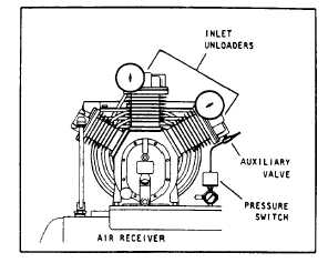
Figure 3-1 Typical Dual Control arrangement.
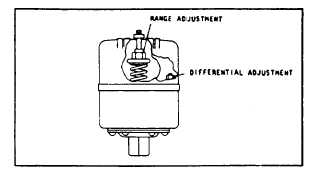
PRESSURE SWITCH ADJUSTMENT
The pressure switch has a Range Adjustment and a
Differential Adjustment. See Figure 3-2. The Cut-out
(Compressor Shutdown) is the pressure at which the switch
contacts open, and the Cut-in (Compressor Restart) is the
pressure at which the switch contacts close.
The cut-out point may be increased by screwing the
range adjustment clockwise. Screwing the range adjustment
counterclockwise decreases the cut-out point. Note the
pressure gauge reading at which the compressor cuts-in and
out and re-establish pressure setting if necessary.
The differential pressure may be increased by
screwing the differential adjustment clockwise. Backing off the
differential adjustment will narrow the span. It is advisable to
have as wide a differential as possible to avoid frequent
starting and stopping of the compressor. Note the pressure
gauge reading at which the compressors cuts-out and re-
establish this point if necessary.
There is interaction between these two adjustments, if
the cut-out is increased, the differential will also increase, or, if
the differential is narrowed, the cut-out will be reduced, etc.
These factors must be considered when adjusting the switch
and compensate for accordingly.
Figure 3-2. Typical pressure switch cut-in and cut-out
adjustment.
page 3- 834