TM 5-3895-374-24-2
the end of the crankshaft. thus when the compressor Is In
operation, centrifugal force acts upon the unloader weights
and they swing outward. (See Figure 4-4). When the
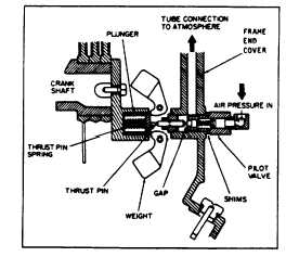
compressor stops. these weights retract, (Figure 4-3)
permitting the thrust pin spring to move the plunger and thrust
pin outward. The thrust pin opens the pilot valve and the
trapped air pressure escapes from the cylinder and intercooler
through a passage in the frame end cover (See Figure 4-5),
through the unloader tube and to atmosphere through the inlet
filter/silencer.
Figure 44. Position of weight and thrust pin when compressor
Is operating..
When the compressor starts, centrifugal force acts
upon the unloader weights and they swing outward. This
permits the plunger and thrust pin to move inward and the pilot
valve to close. The escape path to atmosphere for the
cylinder pressure is now closed and the compressor pumps air
in a normal manner.
If the pilot valve tube line is excessively hot, it is a
good indication that the pilot valve is leaking and adjustment is
required.
PILOT VALVE ADJUSTMENT
To adjust the pilot valve, refer to Figure 4-3, and
proceed as follows:
1
Stop
the
compressor.(Disconnect
the
electrical
supply main switch to prevent accidental start-up.
2.
Remove the pilot valve tube and the tube fittings.
3.
Remove the pilot valve body and all existing shims.
4.
Screw the pilot valve body back into the frame end
cover (without any shims) until contact with the thrust
pin is felt Advance the pilot valve body 1/4 to 1/2 turn
more.
If contact with the thrust pin cannot be felt, the
following steps may be necessary to locate the contact point.
a.
Insert a small instrument (Punch. rod, nail, etc.) into
the end of the pilot valve until it contacts the valve
stem.
b.
While still inserted in the pilot valve, make a mark on
the instrument even with the outside edge of the pilot
valve body.
c.
Keeping the instrument pressed lightly against the
valve stem, screw the pilot valve body into the frame
end cover. When the mark on the instrument starts
moving out away
from the edge of the pilot valve body contact has
been mace with the thrust pin.
d.
Advance the pilot valve body1/4 to 1/2 turn more and
proceed with step five.
5.
Measure the gap between the pilot valve body and
the frame end cover (See Figure 4-3).
6.
Remove the pilot valve body and add enough shims
to fill the gap measured in step five.
7.
Screw the pilot valve body back into the frame end
cover until the body is tight on the shims.
8.
Reconnect the pilot valve tube and tube fittings.
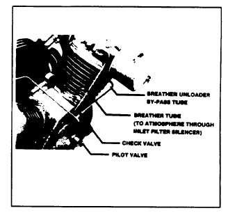
BREATHER/UNLOADER BY-PASS
OPERATION OF THE BREATHER/UNLOADER BY-
PASS The breather/unloader by-pass tube lines eliminates air
pressure build-up in the compressor frame by providing a
passage for the air to escape through the inlet unloader (if
opened) or (if closed) through the check valve (See Figure 4-
5), therefore. by-passing the inlet unloader and escaping to
atmosphere through the inlet filter/silencer.
Figure 4-5. Breather/Unloader By-Pass
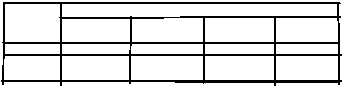
INTERSTAGE PRESSURE CHART (PSIG)
MODEL
COMPRESSOR DISCHARGE PRESSURE (PSIG)
NUMBER
100 PSIG
150 PSIG
200 PSIG
250 PSIG
7.0 kg/cm2
10.5 kg/cm2 14.1 kg/cm}
17.6g/cm2
7100
37-40
40-43
44-47
47-50
3000
37-40
3942
40-43
-----
page 3 - 838