30
0
0
4
6
The wire sizes recommended in the above table are
suitable for the compressor unit. If other electrical equipment is
connected to the same circuit, the total electrical load must be
considered in selecting the proper wire sizes. A burned out
motor due to low voltage may result unless it is properly
protected.
Before wiring the compressor to the power supply, the
electrical rating of the motor, as shown on the motor nameplate,
must be checked against the electrical supply.
If they are not
the same, do not connect the motor.
It is important that the wire used be the proper size and
all connections secured mechanically and electrically.
The
size of the wire shown in the table above is a safe guide.
larger wire will probably be necessary and your electrical
contractor or local electric company should be consulted for
recommendations.
The use of too small wire results in sluggish operation,
unnecessary tripping of the overload relays or blown fuses.
FUSES
Fuse failure usually results from the use of fuses of
insufficient capacity. If fuses are the correct size and still fail,
check for conditions that cause local heating, such as bent, weak
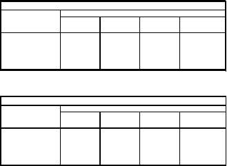
or corroded fuse clips. Refer to the table below for
recommendations on the proper fuse size to be used. Also refer
to the regulations of the National
Electrical
Code
and
requirements of the local code.
DUAL ELEMENT FUSE SIZE-60HERTZ
UL CLASS RK-5 600V
VOLTAGE
MOTOR
THREE PHASE
HORSEPOWER
200
230
460
575
10
40
35
17.5
12
15
70
50
35
20
20
75
70
35
35
25
90
80
40
35
30
110
100
70
40
DUAL ELEMENT FUSE SIZE-60HERTZ
UL CLASS RK-5 600V
VOLTAGE
MOTOR
THREE PHASE
HORSEPOWER
190
220
380
440
10
45
35
25
17.5
15
60
50
30
25
20
80
70
40
30
25
100
80
50
40
30
125
100
60
50
MAGNETIC STARTER
(See Electrical Diagrams On Page 24).
This compressor must be equipped , with a magnetic
starter Note-that the Pressure Switch, the Oil Level Switch and
the
On-Off Switch are wired to the operating coil of the magnetic
starter and serves to interrupt current flow to the motor.
All starters must include thermal overload protection
to prevent possible motor damage from overloading. These
starters are furnished with the manufacturer’s ;instructions for
installation. Ingersoll-Rand cannot accept responsibility for
damages arising from failure to provide adequate motor
protection.
Duplex Models may be equipped with alternating
control circuits for equalizing operation of both compressors
Step 6.
COMPRESSOR STARTUP
Do not connect the compressor piping to your system
at this time.
(A)
Fill the crankcase to the proper level with the correct
grade of lubricating oil. Use only petroleum based oil
for the initial start-up. (See Page 11 for Lubrication
Specifications ) Tighten the oil plug. HAND TIGHTEN
ONLY
(B)
Check compressor rotation by flicking "Start-Stop’
switch. Rotation is shown by arrow on belt guard
back. If rotation is incorrect, interchange two of the
three leads on the three phase motors.
(C)
Prime the condensate trap if supplied on your
compressor. (See Page 18 for Priming instructions A
floor drain should be provided in a nearby location for
condensate drainage. A floor drain is desirable
whether
the
compressor
is
equipped
with
an
automatic condensate trap or not. All compressors
will have water condensate in the air receiver.
Your compressor should now be ready for the initial
startup and checks. Close the service valve and start the
compressor.
Step 7.
PRESSURE REGULATION
Allow the air receiver to build up to pressure for which
you ordered the machine. At
this
pressure,
the
pressure
switch should cause the unit to stop. Open the service valve
and/or drain valve to let pressure in the receiver drop. Note-
the pressure at which the compressor starts/reloads. If the
unit does not Start and Stop/Load and Unload at the correct
pressure,
you
may
need
to
adjust,
the
Pressure
Switch/Auxiliary Valve. (See section III. Regulation, if
adjustments are necessary).
Run the compressor for about 10 minutes by bleeding
air from the receiver to let the unit warm up and observe for
excess vibration or any unusual noise. While the compressor
is running, pull ring on all safety valves to be sure they relieve
and reset properly Do this several times. Retorque all head
bolts to 75 Ft Lbs. (10.4 kg/meters).
IF
YOUR
COMPRESSOR
DOES
NOT
OPERATE
PROPERLY,
SHUT-DOWN
IMMEDIATELY, AND CALL YOUR LOCAL
INGERSOLL-RAND DISTRIBUTOR.
Page 3-832


