TM 5-3895-374-24-2
ANGULAR ALIGNMENT
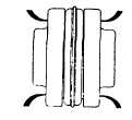
Sleeve Type Elastomer Coupling
Check angular alignment with
a
micrometer or caliper. Measure from
the outside of the flange to the outside
of the other at 90° intervals around the
periphery of the coupling. Determine
the
maximum
and
minimum
dimensions. DO NOT rotate the
coupling. The difference between the
maximum and minimum must not
exceed 0.002 inches.
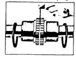
Spring Grid Type Coupllng
Use a spacer bar equal in
thickness to the normal coupling
gap. Insert bar, as shown, to
same depth at 90° intervals and
measure clearance between bar
and hub face with a feeler
gauge.
The
difference
in
minimum
and
maximum
measurements must not exceed
0.002 inches.
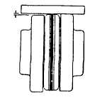
PARALLEL ALIGNMENT
Sleeve Type Elastomer Coupling
Check parallel alignment by placing
a straightedge across the two
coupling flanges and measuring
the maximum offset at various
points around the periphery of the
coupling. DO NOT rotate the
coupling. If the maximum offset
exceeds 0.002 inches, realign the
coupling.
Spring Grid Type Coupling
Align so that a straightedge
rests squarely (or within
0.002 inches) on both hubs
as shown and also at 90°
intervals
around
the
periphery.
D - Piping General
Plastic dirt seals are installed in flanges before the pumps
are shipped and must be removed before installation. Pipes
must be supported independently to ensure no force is
exerted on the pump. Piping should be al least as large as
the pump flange size. Guidelines for piping procedures are
given in the 'Hydraulic Institute Standards” and should be
reviewed before pump installation.
CAUTION
In order to avoid stress build-up due to piping expansion
when handling hot liquids, it is recommended to install
compensation in both suction and discharge lines. For
example, use of flexible piping or a pipe loop will minimize
pipe loads due to thermal expansion.
E - Suction Piping
Suction piping should be as short as possible, be of
ample size to keep friction losses as low as possible, and
contain a minimum number of fittings. A straight run of pipe
(20 times the suction diameter) is recommended immediately
before the pump suction. Check layout against the possibility
of air pockets forming in the suction lines. Suction lines
should be sized for a flow velocity of approximately 6 to 10
ft./sec. On new piping installations, a wire screen
(approximately 32 mesh) should be temporarily installed at the
suction flange to prevent debris (ie: weld slag, dirt, etc.) from
entering the pump. Remove screen after several hours of
system operation.
F - Discharge Piping
Discharge piping should contain both a globe valve and a
check valve. The globe valve is used for starting, stopping,
and flow control. Control flow on the discharge side only. The
check valve will prevent the liquid from flowing back through
the pump from long or high pressure lines.
G - Driver
When sizing motor consider maximum liquid viscosity,
specific gravity and desired pump operating range. The draft
created by a TEFC motor can reduce the temperature at the
shaft seal and bearing housing. The lower the operating
temperature, the longer the expected shaft seal and bearing
life. Coupling guards of the open type are preferred.
SECTION III - OPERATION
A Start-up
Before initial pump start-up or after pump has been shut
down for inspection, observe the following procedures:
1. Pressure test the system for possible leakage.
Maximum Test Pressure 300 PSIG.
2. Check pump rotation. As viewed from the driven
end, the pump rotation is clockwise.
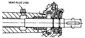
3. Do not run pump dry. Prime the suction line and
pump. Loosen vent plug (item 130). Rotate the
shaft by hand to allow any air in the pump to
escape through the vent and pump discharge.
Tighten vent plug when all air is removed.
CAUTION
If pump is not completely vented, the air trapped in
pump will cause the heat transfer oil to carbonize at
elevated temperatures. The sharp crystal-like deposits
formed, significantly reduce life of seal rings and shaft.
(page 3 - 1143)
Figure 3