TM 5-3895-374-24-2
SECTION I- GENERAL
A - Introduction
This instruction manual is intended to assist those
responsible
with
the
installation,
operation
and
maintenance of SlHI’s ZTN sell cooling centrifugal
pumps. It is recommended that this manual be
thoroughly read before installing or performing any work
on the pump or pumping unit.
B - Receipt of Equipment
Upon receipt, check equipment for shipping or storage
damage. Care should be taken when handling the
pumps. Any damage or shortage at time of delivery
should be reported to the transportation company.
C - Storage
SIHl’s standard shipping and storage preparation is
suitable for protecting the pump during shipping and also
for a short period between installation and start-up. Long
term storage information is available from your local SIHI
representative.
D - Design
SIHl’s self cooling ZTN pump is a non-self priming,
horizontal, single stage centrifugal pump of the back pull-
out design. The back pull-out design allows the removal
of the complete internals without removing the pump
casing from the system. If a spacer type coupling is
used, the pump internals may be moved without
disrupting the motor. V-belt drive arrangement is not
recommended unless a ’jack shaft’ is used. Shaft
sealing is obtained with radial shaft seal rings arranged
in series. External cooling is not required. Pump has
horizontal
suction
and
vertical
discharge
flanged
connections.
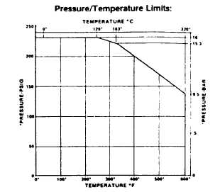
E - Limitations
For maximum operating speed consult your local SIHI
representative.
Pressure
equals
sucton
pressure
plus
ddferential
pressure at shut-off (zero flow) n suction pressure
exceeds 70 PSIG. consult SIHI factory
SECTION II INSTALLATION
A- Location
Locate pump as close as practical to the liquid supply.
Piping should be installed per piping recommendations
of paragraph D., E. & F. Floor space must be sufficient
for inspection and maintenance. Allow sufficient
headroom to permit use of a lifting mechanism, if
required. Pumps are an air cooled design. Provide
adequate ventilation, DO NOT INSULATE PUMP.
B-Foundation
Standard baseplate mounted units are suitable for
installation
on
concrete
pads
or
fabricated
steel
structures. Special baseplates with provisions for
grouting are available. The location and size of
foundation bolt holes are shown on the dimension
assembly drawings which can be provided by your local
SIHI representative.
C- Alignment
The service life of the pump is dependent on good
coupling
alignment.
Flexible
couplings
will
not
compensate for shaft misalignment. If the motor was
mounted by SIHI, the pump and motor were aligned prior
to shipment from the factory. Since baseplates are not
perfectly rigid, handling during shipment, pipe loading
and foundation stresses mandate an alignment check.
Prior to start-up adjust alignment by adding shims under
the motor feet.
The dial indicator method for checking coupling
alignment is preferred, refer to Figures 1 and 2. To
measure parallel misalignment, attach dial indicator to
one coupling hub with the indicator button resting on the
O.D. of the other coupling hub (Figure 1). To measure
angular misalignment, the indicator button rests on the
face of the other coupling hub near the O.D. (Figure 2).
Measure misalignment by rotating the shaft and dial
indicator one full revolution, the other shaft remains
stationary. Record the Total Indicator Reading (T.I.R.).
Parallel and angular misalignment should be limited to
0.002 inches T.I.R.
If a dial indicator is not available, an adequate
alignment is possible using a straight edge, feeler gauge,
micrometer or caliper.
(page 3 - 1142)