TM 5-3895-374-24-2
OPERATION
Refer to the wiring suggestions shown in Bulletin E-
1001 before proceeding to power the FLAME-MONITOR
System. Items such as scanner installation, short circuit
tests and safety information should be reviewed.
Note that for direct spark ignited oil burners,
substitute the words "main oil valve" for "pilot valve".
Start-up (Normal Cycle)
1.
Constant 120V.A.C. should be available to the
L1-L2 terminals on the wiring base.
2.
The operating control circuits (L1 -13)will close,
signaling the burner to start its firing sequence.
3.
Assuming the fuel valve end switch (13-3) is
closed, the burner/blower motor (terminal M)
circuit is energized. The running interlock (limit)
circuit (3-P) will close.
4.
The firing rate motor is driven toward the high
purge open damper position (10-X ckt. made).
5.
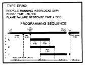
The pre-purge starts counting 30 seconds.
6.
When pre-purge is completed, the firing rate
motor is driven toward the low purge damper
position (10-12 ckt. made).
7.
Following a 30 second delay (to permit the firing
rate motor to move to the low fire position), the
control will wait for the low fire switch (M-D) to
make. When it is made, the trial for ignition
sequence will start. If after ten minutes the M-D
circuit is not made, the control will lockout.
Note: When flame is detected, the message center
will provide a constant readout of the signal
strength.
Flame Signal
0-9
Not Acceptable
10
Minimum Acceptable
20-80
Normal
Normal Shutdown
1.
When the operating control circuit (L1-13)
opens, the main fuel valve is de-energized. The
firing rate motor is driven to the low purge
position.
2.
Following
a
15
second
post
purge,
the
burner/blower motor is de-energized.
3.
The burner is now off and the message center
displays the burner operating history for two
minutes or until another cycle begins.
8.
The trial for ignition period begins with Terminals
5 and 6 being energized simultaneously. This is
known as PTFI (Pilot Trial for Ignition). This
period is ten seconds in duration. If no flame is
detected after ten seconds, the control will de-
energize Terminals 5 and 6, and lockout. If
flame is detected during this 10 second period,
the main trial for ignition sequence will start.
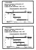
Note: On EP270, PTFI on Terminal 5
is 5 sec. MTFI on Terminal 6 is 10
sec. (30 sec. on EP261) Note Charts
above.
9.
With flame proven at the end of PTFI, the main
trial for ignition (MTFI) period begins. Terminal 7
is energized. Terminal 5 is de-energized 10
seconds later and Terminal 6 is de-energized
after another 5 seconds. (Note the charts above
for exceptions to MTFI timing on EP261 and
EP270).
10.
modulator motor is now sent to the auto position
and is under the control of the proportional
controller. The message center displays a
constant read-out of the flame signal.
Safety Shutdown (Lockout)
The system will lockout for a number of reasons. These
are
described
in
the
following
pages
of
charts.
Whenever a lockout occurs, the message center
displays the reason for the shutdown and the recycle is
possible only when the reset button is depressed and
released. The non-volatile memory will remember the
status of the control even if a power failure occurs.
Important: On initial power-up and on restarts following
power failure, the display will scroll a history message for
15 sec. when using a programmer having a date code
followed by a number greater than "11". (i.e. date code
8740-12)
(page 3 - 1069)


