TM 5-3895-374-24-1
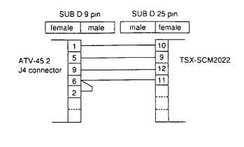
- Example of 20 mA current loop connection with a TSX7 programmable controller, fitted with a
TSX-SCM2022 communication module
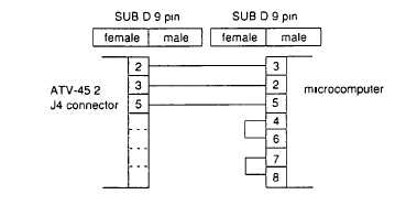
Example of RS232C connection with compatible microcomputer
Structure of the
The adjustment, command, control, and monitoring of the ATV-45 2 by serial link is carried out via
ATV-45 2 data
the exchange of data or (objects) which are specific to that product
Essentially, these comprise
- BITS, called Bi (I = bit number) enabling the carrying out of logic commands
(2 possible states 0 or 1)
Example B7 = braking command bit
- WORDS (16 bits) called Wi (i = word number) used to exchange complete numerical values
(- 2768 to +32767), or, where necessary, a group of 16 independent logic states (these words
are therefore known as registers)
Examples W19 = frequency reference,
W21 = fault register (16 fault bits)
Notation W21,2 assigns the row 2 bit for register W21
Access to the data
Some data is accessible in read and write this comprises the bits and words corresponding to
settings, references and commands As a general rule, this is the data used by the ATV-45 2
On the other hand, data developed by the ATV-45 2 (signalling data, fault data, ) is only accessible
in read Writing of this data Is Illogical and will be refused
(page 3-265)


