TM 5-3895-374-24-2
955-257
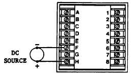
1.10 PROCESS INPUTS - DC VOLTAGE OR CURRENT INPUT
Connect the +DC Input to terminal H and the -DC Input
to terminal F (GND) for any current or voltage DC Input.
The use of shielded twisted pair is recommended to
minimize noise pick up. Never run signal input leads in
the same bundle as supply or load lines.
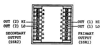
1.11 WIRING FOR SOLID STATE RELAY OUTPUT AND/OR SECONDARY OUTPUT
The PART NUMBER will specify which outputs are included in each unit. Since Solid State Relay and Analog Output use
the same terminals only one type can be provided on each output. Output type is not changeable in the field.
The standard Solid State Relay output is 1 ampere opto-
isolated triac output. An optional 50 mA triac output may
be supplied for either or both SSR outputs (SSR1 AND
SSR2) Maximum voltage for SSR load is 240 VAC. See
case label for type and rating of each output provided.
Current limiting fuses such as Bussman KAA or KAB
series or Gould Shamut form 101 Amptrap (1 AMP) are
recommended to protect the 1 AMP Solid State Relay.
APPLICATION NOTE: WHEN USING THE CONTROLLER SOLID STATE RELAY TO OPERATE AN EXTERNAL
SOLID STATE RELAY OR SENSITIVE COIL RELAY TWO SITUATIONS MAY EXIST.
1.
The leakage current in the 1 amp SSR may be sufficient to cause an external SSR to remain in the conducting
state. To prevent this the 50 mA SSR option is recommended.
2.
The low power draw of the external SSR may cause the controller SSR to turn OFF due to insufficient holding
current. The solution to this is also to use the 50 mA SSR option. An alternate approach is to use a loading
resistor across the external SSR or relay terminals to increase the current.
ECLIPSE INSTRUMENTATION DIVISION
page 3 - 1085


