TM 5-3895-374-24-2
955-257
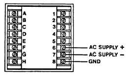
1.7 AC SUPPLY WIRING
Connect the AC line power to the rear terminals as
shown in this diagram. The unit is normally wired for
120 VAC operation. Refer to the label on the unit for
proper AC supply voltage rating. Maximum input current
at 120 VAC, 50/60 HZ is 115 mA AC. Other voltages
are also available.
Check and be sure.
CAUTION: APPLYING HIGHER SUPPLY VOLTAGE TO A UNIT NOT RATED FOR THIS VOLTAGE WILL
RESULT IN DAMAGE TO THE CONTROLLER.
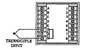
1.8 THERMOCOUPLE INPUT
Connect the RED thermocouple wire or extension lead to the unit rear panel terminal "F" (T/C Return -). Connect the
remaining thermocouple lead, differing in color depending upon the thermocouple type to the rear panel terminal "H" (+
T/C). No external connection is made to terminal "G".
It is very important that the thermocouple extension leads be of the same type as the thermocouple specified in the part
number, that all connections be clean and tight and preferably shielded twisted pair to minimize noise pick up. Never run
signal input leads in or near the same bundle as supply or load lines. Maximum loop resistance of the thermocouple circuit
should not exceed 100 ohms.
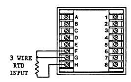
1.9 RTD INPUT (100 OHM PLATINUM, 3850 ppm)
Connect the RTD sensor per the following figure for a 3
wire RTD input. If a two wire RTD is used, strap
terminals F and G together and connect the RTD
between terminals G and H.
Note that the RTD leads can be extended with copper
wire provided they are the same length and diameter and
run in a common conduit. Maximum extension lead
resistance shall not exceed 10 ohm.
The use of the shielded twisted pair is recommended to minimize noise pick up. Never run signal input leads in or near the
same bundle as supply or load lines. For 2 wire RTD we recommend running 3 wires to the RTD and connecting the F
and G wires together as near the RTD as possible.
ECLIPSE INSTRUMENTATION DIVISION
page 3 - 1084