TM 5-3895-374-24-2
955-257
SECTION 1 - INSTALLATION
1.1 UNPACKING
Remove the unit from the shipping carton. Check to see that the unit has not been damaged in shipping. If equipment is
damaged in transit, report any damage to and file a claim with the carrier.
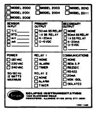
1.2 IDENTIFICATION
Refer to the case mounted top label on each unit for
proper identification of supply voltage, Output(s),
Alarm/Timer and Sensor type before proceeding with the
wiring.
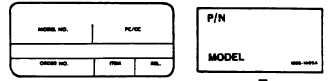
1.3 PART NUMBER
Each controller is assigned a ten-digit PART NUMBER at
the factory or by the Modification Center that specifies
its hardware and software configuration. The part
number is shown on the production label mounted on top
of the case immediately behind the front bezel.
The PART NUMBER is also located on, a label on the
mother board at the rear of the front bezel assembly. To
read this label, the electronic assembly must be pulled
out of the case. With the power off, squeeze the tabs on
each side of the front bezel and pull the electronic
assembly forward enough to expose the P.N. label. You
do not have to remove the assembly from the case to
read this label.
(1) MODEL
(1) MODEL
(2) PRIMARY OUTPUT
(4) INPUT
(5) ALARM/TIMER1(7) OPTIONS
E0 2000 No Communications
EA 2003 No Communication
0 No Primary
00 J Thermocouple
0 No Alarm
00 No options
E1 2000 Remote Analog Setpoint
EB 2003 Remote Analog Setpoint
1 Primary Heat SSR ON/OFF
01 K Thermocouple
1 HI Process
XX Any special.
E2 2001 RS232C Non-isolated
EC 2003 R5232C Non-isolated
2 Pri. Cool SSR ON/OFF
02 R Thermocouple
2 LO Process
Factory
E3 2001 RS232C Isolated
ED 2003 RS232C Isolated
3 Pri. Heat SSR Prop
03 S Thermocouple
3 HI Deviation
assigns final
E4 2001 RS422 Non-isolated
EE 2003 RS422 Non-isolated
4 Pri. Cool SSR Prop
04 T Thermocouple
4 LO Deviation
numbers.
E5 2001 RS422 Isolated
EF 2003 RS422 Isolated
S Pri. Heat 4-20mA DC
05 N Thermocouple
5 On Timer
E6 2001 20mA Current(isolated)
EG 2003 20mA Current(isolated)
6 Pri. Cool 4-20mA DC
06 E Thermocouple
6 OFF Timer
7 Pri. Heat 0-5 VDC
07 B Thermocouple
7 Deviation band
Z0 2002 No Communication
ZA 2004 No Communications
8 Pri. Cool 0-5 VDC
08 PLATINEL II T/C
Z1 2002 Remote Analog Setpoint
ZB 2004 Remote Analog Setpoint
09 Ni/Ni 18%Mo T/C
(6) ALARM TIMER
Z2 2002 RS232C Non-isolated
ZC 2004 RS232C Non-isolated )
(3) SECONDARY OUTPUT
10 W5%Re/W26%Re T/C
Z3 2002 RS232C Isolated
ZD 2004 RS232C Isolated
11 W3%Re/W25%Re T/C
0 No Alarm
Z4 2002 RS422 Non-isolated
ZE 2004 RS422 Non-isolated
0 No Secondary
12 W/W26%Re T/C
1 Hl Process
Z5 2002 RS422 Isolated
ZF 2004 RS422 Isolated
1 Sec. Heat SSR ON/OFF
20 1” RTD 100W Pt
2 LO Process
Z6 2002 20h Current(isolated)
ZG 2004 20mA Current(isolated)
2 Sec. Cool SSR ON/OFF
21 0.1' RTD 100W Pt
3 HI Deviation
4 Sec. Cool SS Prop
40 0-5 Volts DC
4 LO Deviation
6 Sec. Cool 4-20Ma DC
60 4-20mA DC
5 ON Timer
7 Sec. Cool 0-5 VDC
6 OFF Timer
7 Deviations Band
9 Seq. Option
ECLIPSE INSTRUMENTATION DIVISION
page 3 - 1081