TM 5-3895-374-24-2
6-1 Assembly of trolley
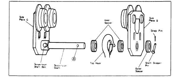
1) In case of plain and geared trolleys, insert the suspension
shaft into the side-plate G, and fix it with the bolt for
suspension shaft.
2) Insert the suspension shaft into the side-plate S and insert
the outer spare adjusting spacers outside of the side-plate
S, and insert the stopper pin into hole IX of the suspension
shaft. (Do not put in a split pin, as the stopper pin may be
pulled out in adjusting the trolley width and mounting the
trolley on the beam.)
3) When connecting a geared trolley to an electric chain hoist,
take care so that the hand chain may be on the opposite side
of the power supply cable.
Fig. 4
(page 3 - 883)