TM 5-3895-374-24-2
belt only to the point where its top surface is even
with the bottoms of the other undeflected belts.
6.
A new set of belts should be first tensioned about 1/3
greater than normal to allow for stretch and wear-in.
Before putting the drive into normal operation,
increase the tension as obtained above by a small
amount. Recheck after each 8 hour operating period
during the first 50 hours, and adjust as necessary.
Before operating the drive under power to check
initial belt tension, first remove covers from the blower
connections. Make sure the interior is still clean, then
rotate the shaft by hand. Place a screen over the inlet
connection to prevent anything being sucked into the
blower while it is operating, and avoid standing in line
with the discharge opening. Put oil in the gearhouse per
instructions under LUBRICATION.
Before connecting piping, remove any remaining
antirust compound from blower connections. Piping
must be clean and should be sized so that the air velocity
will not exceed 75 feet per second 123 m per second).
Pipe used should be no smaller than blower connections.
In addition, make sure it is free of dirt, scale, cuttings,
weld beads, or foreign materials of any kind.
To further guard against damage to the blower.
especially when an inlet filter is not used, install a
substantial screen of 16 mesh backed with hardware
cloth at or near the inlet connections. Make provisions to
clean this screen of collected debris after a few hours
operation. It should be removed when its usefulness has
ended, as the wire will eventually deteriorate and small
pieces going into the blower may cause serious damage.
Pipe threads or flanges must meet the blower
connections accurately and squarely. Do not attempt to
correct misalignment by springing or cramping the pipe.
In most cases this will distort the blower casing and
cause impeller rubbing. In severe cases it can prevent
operation or result in a broken drive shaft. For similar
reasons, piping should be supported near the blower to
eliminate dead weight strains. Also, installation of
flexible connectors or expansion joints is recommended.
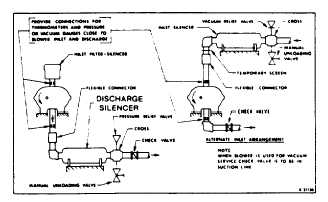
Figure 4 represents in diagram form a blower
installation with all accessory items that might be
required under various operating conditions. Inlet piping
should be completely free of valves or restrictions.
When a shut-off valve (not shown) cannot be avoided,
make sure a full size vacuum relief is installed near the
blower inlet. This will protect against blower overload
caused by accidental closing.
Need for an inlet silencer will depend on blower
speed and pressure, as well as sound-level requirements
in the general surroundings. An inlet filter is normally
recommended, especially in dusty or sandy locations, for
blower protection. A discharge silencer is also normally
suggested. Specific recommendations on silencing can
be obtained from the nearest Distributor. Silencers
should be mounted as close to blower as possible.
Discharge piping requires a pressure relief valve,
and should include a manual unloading valve to permit
starting the blower under no-load conditions. Reliable
pressure/vacuum gauges and good thermometers at
both inlet and discharge are recommended to allow
making the important checks on blower operating
conditions. If the demand is constant, but somewhat
lower than the blower output, excess may be blown off
through the manual unloading valve.
In multiple blower installations when two or more
units discharge into a common header, use of check
valves is recommended. These should be of a direct
acting or free swinging type, with one valve located in
each blower
Figure 4-Installation with Accessories.
discharge line. Properly installed, they will protect
against damage from reverse rotation caused by air
backflow through an idle blower.
After piping is completed, and before applying power,
rotate the drive shaft by hand again. If it does not move
with uniform freedom, look for uneven mounting, piping
strain, excessive belt tension or coupling misalignment.
Do not operate the blower more than briefly at this time
because of possible inadequate oil supply in the
gearhouse. Read LUBRICATION section.
LUBRICATION
A simple but very effective lubrication system is
employed on UNIVERSAL RAI® blowers. At the drive
shaft end the bearings are grease lubricated using
hydraulic pressure relief fittings. These relief fittings vent
any excess grease, preventing pressure build-up on the
seals. A restriction plug and metering orifice prevent
loss of lubricant from initial surges in lubricant pressure
but permit venting excess lubricant under steadily rising
pressures.
The blind end bearings and timing gears are
enclosed by a gearhouse located opposite the drive end
of the blower. In a side outlet blower, the lower timing
gear functions as an oil slinger, carrying lubricant to the
upper timing gear and providing splash lubrication for the
bearings. Pressure within the gearbox is vented through
the breather vent plug 125).
The above description also applies in general to the
top or bottom outlet style blower, the principal difference
being that both gears dip into the oil sump.
Before starting blower, be sure oil has been put in
gearhouse, as ALL OIL WAS DRAINED FOLLOWING
SHOP TESTS. For recommended lubricating oil see
Table 2. Use a good grade industrial type rust, oxidation.
and foam inhibited, non-detergent oil.
page 3-806