TM 5-3895-368-14&P
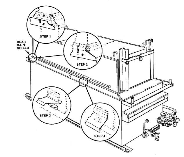
Figure 2-2. Installing Rain Shields.
NOTE
Install flange joint hexagon head
capscrews and nuts finger tight, until
all connections have been made then
tighten all hardware securely.
e. For operation as a single unit installation, install
connecting heat transfer piping and asphalt discharge
hose as shown in figure 2-5.
f. For installations of multiple units make
interconnections of heat transfer piping and asphalt
hoses as shown in figure 2-6.
g. Inspect all connections to insure that they are
tight and that the storage tank drain cap, in rear of
storage tank, is installed.
h. Install load ramp (1, Figure 2-7), platform (13)
and ladder (7) as shown in figure 2-7. Adjust leg
extensions (11) so pads rest on ground or blocking while
keeping platform (13) as level as possible. Initially
tighten all fasteners finger tight, when all adjustments
and components are in place tighten fasteners securely.
i. Install the load platform upper-structure (Figure
2-8) as follows:
(1) Secure the up-right supports (6) to the
load platform (13, Figure 2-7) noting that original
supports were shipped with only one of the four drilled
through the side flange. That support must be installed
at the right-front position on the load platform.
(2) Carefully position the rear cross-beam
(1, Figure 2-8) and front cross-beam (4) over up-rights
(6) as shown with the mounting holes for the trolley rail
(5) offset to the right side of the melter. Secure cross-
beams with 5/8 inch capscrews (10), lockwashers (9),
and nuts (8).
2-5