TM 5-3895-368-14&P
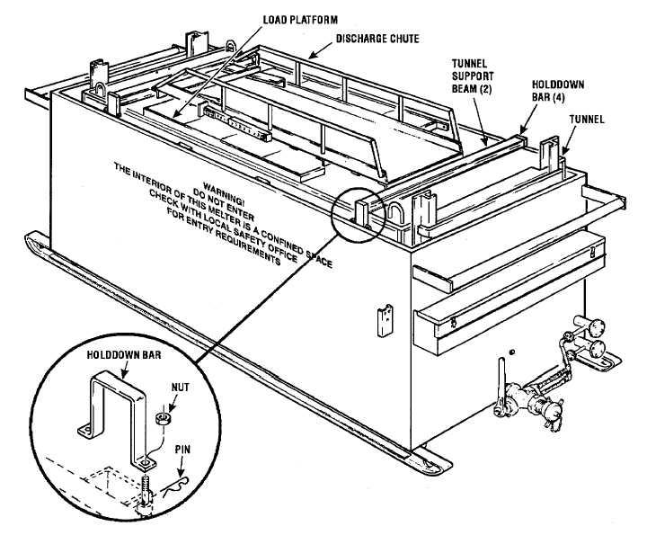
Figure 2-1. Asphalt Melter in Shipping Configuration.
2-4.
Installation.
a. With a suitable hoist and a four-point sling
attached to lifting eyes of tunnel, lift the tunnel into
position over the storage tank. Align the tunnel so that
the support rails (channels) on bottom of tunnel are
directly over the tunnel support beams and lower the
tunnel onto the beams. Center the tunnel between the
sides of the storage tank.
NOTE
The front of the tunnel can be
determined by looking at the cable
pulleys welded to the support bar
near top of door. The end of tunnel
with pulley on the left as you look at
it is the front.
b. Install the six-piece rain shield around base of
tunnel as shown in figure 2-2. The rear rain shield must
be installed first, then the side rain shields, working from
the rear forward, with the front rain shield (3, Figure 2-3)
installed last.
c. Install thermometer (Figure 3-1) by threading
into opening in front wall of storage tank.
d. Install heat transfer piping and asphalt jacketed
valve as shown in figure 2-4. Insure that gaskets at each
flanged coupling are not damaged or folded in such a
way that would hinder sealing the joints.
2-4