TM 5-3895-374-24-2
BULLETIN E-64
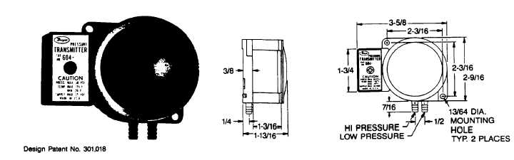
SERIES 604
DIFFERENTIAL PRESSURE TRANSMITTER
Specifications - Installation and Operating Instructions
The Dwyer Series 604 differential pressure transmitter
converts air or compatible gas pressure into a standard
4-20 mA output signal for pressure ranges from 0-0.1 up
to 0-120" w.c. Each of the models overlap in range, so
that any range within these limits can be achieved by
adjustment of the span and zero controls. Convenient
two-wire operation simplifies installation and expands
application .,flexibility over three and four wire units.
Positive, negative or differential pressures can be
measured within an accuracy of ±2% of span. The
Series 604 transmitter uses a diaphragm linked to a
cantilevered leaf spring as in the Dwyer Magnehelic®
gage. However, the mechanical amplification achieved
by the magnet/ helix/pointer components in the indicating
gage is eliminated. Instead a silicon strain gage is
cemented to the range spring. As this is flexed by
applied pressure via the diaphragm, a resistance change
is produced which is conditioned and converted into a 4-
20 mA output signal.
For applications requiring direct pressure or percent of
full span readings, the optional A-701 digital readout
makes an ideal companion device. It provides a bright
.6" high, 3-1/2 digit, LED display while also supplying
power to the Series 604 transmitter.
For additional information on these and other Dwyer
pressure transmitting instruments, refer to Bulletin E-50.
SERIES 604 TRANSMITTER MODELS & RANGES
MODEL
RANGES IN INCHES OF WATER
NUMBER
AS STOCKED
MIN. RANGE
MAX. RANGE
604-0
0-0.5
0-0.1
0-1.0
6041
0-2.0
0-0.5
0-4.0
604-2
0-10
0-2.0
0-20
604-3
0-50
0-15
0-120
SPECIFICATIONS
GENERAL
PERFORMANCE AT 70F
4 mA
Max. Pressure
50 PSIG surge, 30 PSIG continuous to either pressure
connection
Zero Output:
20 mA
Media Compatibility
Air & noncombustible, noncorrosive
gases
Full Span Output:
±2% Full
ELECTRICAL
Accuracy (Includes linearity, hysteresis and repeatability.)
Span Output
Power Supply: 12.3 to 35 VDC
Span & ZeroAdjustable to 0.05%
Output Signal: 4 to 20 mA D.C
ENVIRONMENTAL
20 to 120F
(limited at 38 mA)
Operating Temperature (dry air)
Loop Resistance:
0 to 1135 ohms
Thermal Errors:
±1%/50F typical
R Lmax+ Vps-12.3V
MECHANICAL
6 oz.
Warm Up Time: 10 Minutes
Weight:
Current Consumption
38 mA max. DC
Span &
ZeroProtected potentiometers.
Adjustments:
Pressure Connections:
Barbed, for 3/16”
I.D. Tubing
STANDARD ACCESSORIES
(2) #10 x 1" Pan head sheet metal screws
(page 3-709)