TM 5-3895-374-24-2
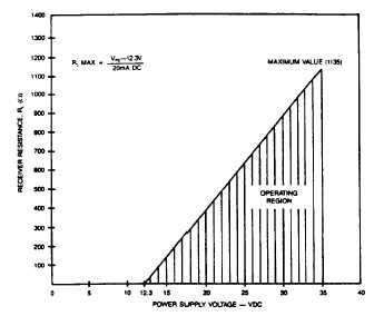
FIGURE C
The maximum length of connecting wire between the
transmitter and the receiver is a function of wire size and
receiver resistance. That portion of the total current loop
resistance
represented
by
the
resistance
of
the
connecting wires themselves should not exceed .,j% of
the receiver resistance. For extremely long runs (over
1,000 feet), it is desirable to select receivers with higher
resistances in order to keep the size and cost of the
connecting leads as low as possible. In installations
where the connecting run is no more than 100 feet,
connecting lead wire as small as No. 22 Ga. can be
used.
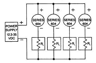
FIGURE D
Several Series 604 transmitters can be operated with a
single power ply as depicted above in Figure D. Be
careful to specify a supply with sufficient capacity. The
minimum current requirement at a given voltage can be
calculated by multiplying the number of units x 20 mA. In
the example shown this would be 4 x 20 or 80 mA
minimum.
PRESSURE RANGING
Each Series 604 Transmitter is factory calibrated to the
range given in the model number chart. However,
special calibration is also available. If this is the case,
the transmitter will be so marked. For purposes of
clarification in these instructions, range is defined as that
pressure which applied to the transmitter produces 20
milliamps of current in the loop. Zero pressure is always
assumed to be 4 milliamps.
If a transmitter pressure range other than that supplied is
required, the following re-ranging procedure should be
followed:
1.
With the transmitter connected to the companion
receiver per the instructions above, an accurate
milliammeter with a full scale
reading
of
approximately 30 milliamps should be inserted in
series with the current Ioop. A controllable
pressure source capable of achieving the
desired range should be connected to the high
pressure port of the transmitter and teed into an
accurate
reference
pressure
gage
or
manometer. Be sure to vent the low pressure
port to atmosphere. The instrument must be
ranged in the same position in which it will be
used. Vertical mounting recommended.
2.
Apply electrical power to the system and allow it
to stabilize for 10 minutes.
3.
With no pressure applied to transmitter, use
"zero" adjustment to set loop current at 4 mA.
4.
Apply full range pressure and set loop current at
20 mA using "span" adjustment.
5.
Relieve
pressure
and
allow
transmitter
to
stabilize for 2 minutes.
6.
Zero and span adjustments may be interactive
so repeat steps 3 through 5 until zero and full
range
pressures
consistently
produce
loop
currents of 4 and 20 mA respectively.
7.
Remove the milliammeter from the current loop
and proceed with final
installation
of
the
transmitter and receiver.
(page 3-711)