TM 5-3895-374-24-2
MODEL A-701 DIGITAL READOUT
WIRING CONNECTIONS
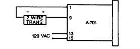
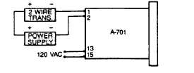
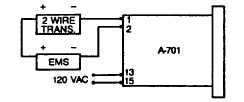
Refer to accompanying circuit schematics for typical
wiring arrangements. Note that the A-701 Digital
Readout contains a 24V DC @ 50mA DC internal power
supply capable of operating most Dwyer transmitters.
See figure C. With external power supplies or as part of
an EMS (energy management system), wire according to
drawings D and E. All three circuits require 120V AC line
current to terminals 13 and 15. Solder all wires to edge
connector and use heat shrink tubing to insulate each
terminal. Attach connector to edge of circuit board.
2-WIRE CONNECTION USING A-701 24 VDC @
50mA. OUTPUT INTERNAL POWER SUPPLY
FIGURE C
2-WIRE CONNECTION USING EXTERNAL
POWER SUPPLY.
FIGURE D
A-701 INDICATOR IN A SERIES LOOP WITH
AN ENERGY MANAGEMENT SYSTEM (EMS).
FIGURE E
MAINTENANCE
Following final installation of the A-701 Digital Readout
no routine maintenance is required. Periodic checks of
calibration
are
recommended
using
procedures
described above. Units are not field serviceable and
should be returned to factory if repair is necessary.
FR NO. 01-440697-0
Litho in USA 7/91
(page 3-714)