TM 5-3895-374-24-2
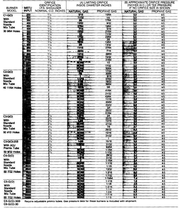
Table 10
Gas Burner Orifice Sizing Information (See pages 32, Fig. 33 for side orifice detail.)
(A)
orifices are not generally used on natural gas for higher
ratings of On/Off, Low-High-Off, Low-High-Low units or
any ratings of modulating units as the butterfly functions
as a variable orifice. Modulating LP. gas units require a
properly sized limiting orifice.
(B)
Approximate pressure for initial start-up. Final pressure
should be determined after checking actual flow with gas
meter. Stack temperature. CO/2, O/2 and firebox
pressure will help in determining actual input when gas
meter is not available for this unit.
Consideration should be given to magnitude of furnace pressure.
Furnace pressure must always be added to above orifice
pressures, which are based on neutral furnace pressure.
Burners equipped with optional adjustable premix tubes
will provide flows shown at slightly lower pressures.
Most fixed premix tubes will require slightly higher
pressures. When available supply pressure is too low to
provide above, orifice may be enlarged or removed and
proper adjustment made on gas pressure regulator.
(page 3 - 985)