TM 5-3895-374-24-2
7.
High turn down ratios are a distinct advantage of internal
bypass systems. It is possible, however, to adjust for a
low fire so small that the flame is being “chilled.” The fire
will look excellent and appear bright and uniform, but a
combustion efficiency test will reveal high smoke content
and low CO2. To correct this situation, increase the oil flow or
decrease the air, or both. Be sure to test with proper
instruments to ensure good, clean efficient combustion
throughout the firing range.
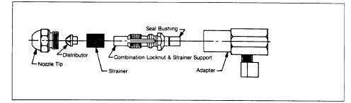
Figure 29
Internal Bypass Oil Nozzle Components
Table 8
OIL NOZZLE FLOW RATE CHARTS
Internal By-Pass Nozzle System (Monarch F-80 BPS)
Flow Rate vs Pressure
100 PSIG
Nominal
U.S. Gallons Per Hour #2 Fuel Oil
300 PSIG
Nominal
Rating GPH
By-Pass
Closed
BY-PASS PRESSURE PSIG
By-Pass
Pressure with
By-Pass
Closed
Capacity GPH
By-Pass
Closed
0
60
120
180
220
.75
.40
.80
80
1.00
1.00
.65
.95
1.65
125
1.70
1.50
.90
1.30
2.20
135
2.50
2.00
1.45
2.00
3.10
135
3.30
2.50
1.10
1.85
3.40
155
4.25
3.00
1.75
2.25
3.75
160
4.80
3.50
2.20
2.75
3.90
175
6.20
4.00
2.45
2.70
4.10
6.35
185
6.60
4.50
2.90
3.45
4.50
7.70
205
7.80
5.00
3.40
3.65
4.90
7.65
195
8.25
5.50
3.05
3.50
4.65
180
9.35
6.00.
2.90
3.15
4.45
5.95
215
10.40
6.50
3.30
3.60
4.80
6.30
11.40
225
11.55
7 00
2.75
3.60
5.40
7.90
220
10.60
7.50
3.55
4.10
5.40
7.60
205
12.35
8.00
3.10
3.55
5.05
7.65
200
12.50
9.00
3.40
3.95
5.90
9.10
200
14.45
9.50
3.60
4.30
6.20
9.45
210
15.45
10.50
3.65
4.30
6.50
9.80
220
16.00
12.00
4.30 .
4.90
8.10
12.50
210
19.40
13.50
6.00
6.60
10.80
18.50
210
23.30
15.50
6.30
6.80
9.00
13.90
220
25.50
17.50
6.80
7.30
10.90
17.00
22.40
225
28.20
19.50
6.20
6.70
10.30
17.40
23 60
235
30.60
21.50
7.80
8.20
11.90
19.40
26.40
240
33.50
24.00
8.40
9.20
14.40
24.30
33.40
230
35.10
28.00
9.00
11.10
21.10
40.20
215
48.70
30.00
8.10
11.30
23.20
38.00
50.60
225
51.60
35.00
10.80
15.70
32.60
38.00
200
58.50
40.00
16.60
22.20
40.50
54.30
190
68.30
45.00
23.10
29.40
49.60
66.00
180
76.20
50.00
29.50
37.40
61.90
165
83.90
Some burners in sizes from 30 to 75 GPH may use Delavan 30630 nozzles. C6-GO-30 and C6-0 burners use Delavan 30637 nozzles. Data
for these nozzles is included with shipment.
(page 3 - 982)