TM 5-3895-374-24-1
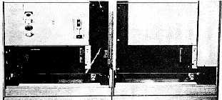
Joining Sections
1-7
Space bar kits are provided for each shipping split.
For factory shipping splits, the splice bar kits are
located in the right-hand section
I-8
Provisions must be made for fastening structures
to the floor See installation procedure 1-14, page
10 for layout of fastener locations
NOTE: Although sect ors are 4ree-standilg, floor
fastening prevents movement and damage to conduit
connections.
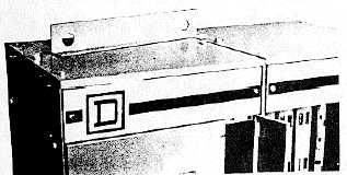
I-9
Supporting the motor control center by its base
channels and/or lifting angles, the motor control
center can now be lifted into place The front edges
of the base channels must be aligned to form a
continuous front.
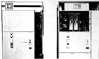
I-10
If desired, the lifting angles which are now at -he
top of each shipping block may be removed
However, the V2" bolts used to attach the lifting
angles must be re-installed
(Page 3-124)