TM 5-3895-374-24-1
Positioning and Splicing
I-12
Motor control centers should be lifted into place
supporting the equipment by Its base channels
and/or lifting angles. The front edges on the
base channel should be aligned to form a
continuous front. Lifting angles, which are
provided at the top of each shipping block may
be removed, if desired, but the l/2" bolt used to
attach the lifting angles should be replaced
Splice bar kits are provided for each shipping
split and
are
connected
by
the
following
procedure:
1.
Remove top unit and door or filler cover
In section to right of shipping split (It is not necessary to
remove top unit or filler cover on left side of shipping
split).
2
Slide sections into place, align and bolt frames
together.
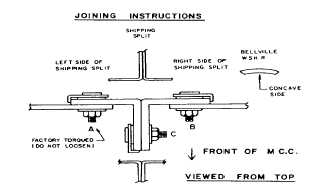
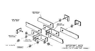
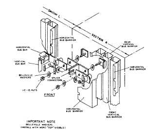
3.
After frames have been bolted together loosen
nut ’B’ insert clamp ’C’ c/w bellevllle washers (Care must
be taken to insure concave sides of bellevllle washers
are against bus bars ) When clamp ’C’ and washers are
in place install nut ’C’ and torque to 50 ft lbs Do not
loosen nut ’A’ as it is factory torqued to 50 ft lbs
4 After nut ’C’ Is torqued, re-tighten nut ’B’ and torque to
50 ft lbs
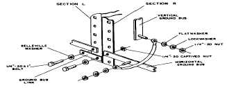
Ground Bus Splicing
I-13
Install the horizontal ground bus splice bar as
shown Use the 1/4" - 20 bolts, flat washers and
lock washers supplied in the splice bar kit.
(Page 3-126