TM 5-3895-374-24-2
TECHNICAL SERVICE MANUAL
SECTION TSM000
INSTALLATION, START UP, TROUBLESHOOTING,
PAGE 1
VIKING
PREVENTATIVE MAINTENANCE, DO’S & DON’TS
ISSUE C
PUMP
Suggested Reference: Hydraulic Institute Handbook, 14th
Edition.
INSTALLATION
General
Before installation is started a few items of a general nature
should be considered.
1.
Location - always locate the pump as close as
possible to the supply of liquid to be pumped. Locate
it below the liquid supply if at all practical. Viking
pumps are self priming but the better the suction
conditions the better the performance.
2.
Accessibility - the pump should be located where it is
accessible for inspection, maintenance, and repair.
For large pumps, allow room to remove the rotor and
shaft without removing the pump from the base.
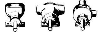
3.
Port Arrangement - since the pumps have different
port arrangements depending on the model, port
location should be checked before starting the
installation. The ports may be upright, opposite or at
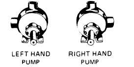
right angles to each other, see Figure 1. The right
angle ports are normally right-hand, see Figure 2;
some
models
are
available
with
left-hand
arrangements; still other models are available with
the right angle ports located in any one of eight
positions including righthand and left-hand.
FIGURE 1
FIGURE 2
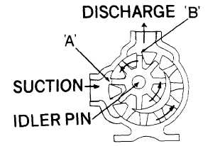
4.
Suction/Discharge - shaft rotation will determine
which port is suction and which discharge. A look at
Figure 3 will show how rotation determines which port
is which; as the pumping elements (gears) come out
of mesh, point "A" on Figure 3, liquid is drawn into the
suction port; as the gears come into mesh, point "B",
the liquid is forced out the discharge port. Reversing
the rotation reverses the flow through the pump.
When determining shaft rotation, always look from
the shaft end of the pump. Unless otherwise
specified, rotation is assumed to be clockwise (CW),
which makes the suction port on the right side of the
pump. The idler pin, which is offset in the pump
head, should be properly positioned toward and an
equal distance between the port connections.
FIGURE 3
5.
Pressure Relief Valve - the Viking pump is a positive
displacement pump. This means that when the pump
is rotated, liquid will be delivered to the discharge
side of the pump. If there is no place for this liquid to
go - discharge line is blocked or closed -the pressure
will build up until the motor stalls, the drive equipment
fails, a pump part breaks or ruptures, or the piping
bursts. To prevent the possibility of any one or more
of these things happening in case of unintentional
closing of the discharge line, the use of a pressure
relief valve is recommended. A pressure relief valve
will relieve the pressure at a predetermined value,
thus protecting the entire system.
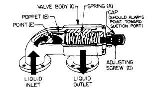
CUT-AWAY OF VIKING INTERNAL PRESSURE
REUEF VALVE FIGURE
4
The pressure relief valve mounted on Viking pumps
and most in-line valves are of the spring loaded
poppet design. See Figure 4. The spring (A) holds
poppet (B) against the seat in the valve body (C) with
a given force determined by the spring size and by
how tightly it is compressed by the
VIKING PUMP, INC. • A Unit of IDEX Corporation • Cedar Falls Iowa 50613 U S A
Page 3 - 1202