TM 5-3895-374-24-2
SECTION 20
BULLETIN 20.96 R
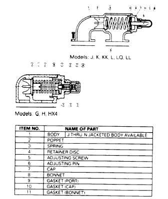
RELIEF VALVE INSTRUCTIONS
DISASSEMBLY
(1)
Remove valve bonnet.
(2)
Measure and record the length of extension of the
adjusting screw.
(3)
Loosen the adjusting nut and rotate the adjusting
screw counter-clockwise until the spring pressure is
released fully.
(4)
Remove the cap, retainer disc spring and poppet,
from the valve body Clean and inspect all parts for
wear or damage and replace if necessary
REASSEMBLY
Simply reverse the procedure outlined under disassembly If
the valve has been removed from the pump for inspection, be
sure to replace in the same position The bonnet should point
towards the suction port.
PRESSURE ADJUSTMENT
The pressure setting on any relief valve supplied on a pump
should be adjusted and/or checked for setting on individual
applications as the valve is supplied with a spring that is
adjustable within a given pressure range.
To check the setting place a pressure gauge in the discharge
line between the pump and discharge gate valve. Slowly close
the gate valve until full bypass pressure is obtained. This
pressure should be greater than the normal operating
pressure. If not. it can be increased by turning the relief valve
adjusting screw inward until the desired setting Is achieved.
After the relief valve has been set. the locking nut can be
tightened and the bonnet can be re-assembled.
When ordering relief valve springs, be sure to state the
maximum operating pressure required.
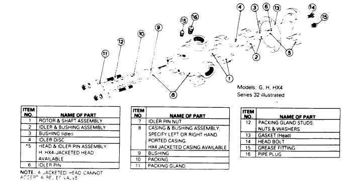
REPLACEMENT PARTS LIST
Page 3 - 1200