TM 5-3895-374-24-2
955-257
5.7 20 mA CURRENT LOOP INTERFACE (CONTINUED)
NOTES:
1.
Symbol A indicates 20 mA current source provided by others.
2.
Less than 2.3 V (Transmit) and 1.0 V (Receive) drop across contacts while
marking.
3.
Maximum voltage that can be applied across Transmitter or Receiver
Terminals is 24 V. Maximum current is 30 mA.
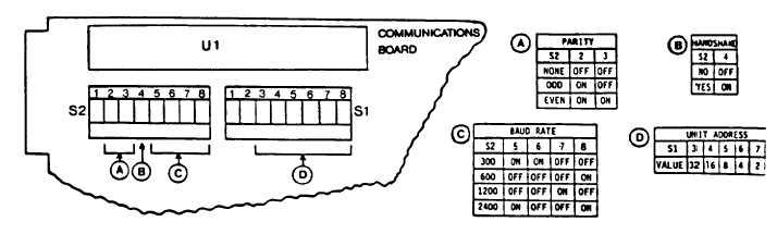
5.8 FORMAT SELECTION SWITCHES
Format selector switches mounted on the communications circuit board inside the controller allow the user to select
Parity, Baud Rate and Unit Address to fit the application. The switch options are:
PARITY:
Even. odd or no parity (factory set at NO PARITY)
BAUD RATE:
300, 600, 1200 or 2400 (factory set at 1200)
UNIT ADDRESS:
0 to 63 (factory set at ADDRESS 0000)
Handshake:
YES or NO (factory set at NO HANDSHAKE)
To access these switches, turn power to the controller OFF. Press in the tabs on each side of the front bezel and pull
the electronic assembly forward enough to expose the switches. DO NOT REMOVE the assembly from the case.
Carefully note the type of switch action. Rocker switch action is PUSH IN to activate. Slider switch action is slide UP
or DOWN to activate. Follow the markings on the switch for the correct switch position for ON (CLOSED, HI, 1) or
OFF (OPEN, LO, 0). Use a pencil, pen tip or bent paper clip to set desired switch position.
ALL UNUSED SWITCHES MUST BE SET "OFF"
ECLIPSE INSTRUMENTATION DIVISION
page 3-1109