TM 5-3895-374-24-1
INSTALLATION
1.
Replace the plastic plugs that protect the threaded holes
in the reducer housing with the eyebolt supplied with the
reducer
2.
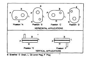
Determine the running position of the reducer (See Fig 1)
Note that the reducer is supplied with either 4 or 7 plugs, 4
around the sides for horizontal Installations and 1 on each
face for vertical Installations. These plugs must be arranged
relative to the running positions as follows:
Horizontal Installations-Install the magnetic drain plug In the
hole closest to the bottom of the reducer Throw away the tape
that covers the filler/ventilation plug in shipment and install
plug in topmost hole. Of the 3 remaining plugs on the sides of
the reducer, the lowest one Is the minimum oil level plug If
output rpm is lower than 10, consult factory for oil level.
Vertical Installations-Install the filler/ventilation plug In the
hole provided in the top face of the reducer housing. Use the
hole in the bottom face for the magnetic drain plug Of the 5
remaining holes on the sides of the reducer, use a plug in the
upper housing half for the minimum oil level plug.
The running position of the reducer In a horizontal
application is not limited to the four positions shown in Figure
1. However, If running position is over 200 either way from
sketches, the oil level plug cannot be safely used to check the
oil level unless during the checking the torque arm IS
disconnected and the reducer Is swung to within 200 of the
positions shown In Figure 1. Because of the many possible
positions of the reducer, it may be necessary or desirable to
make special adaptions using the lubrication fitting holes
furnished along with other standard pipe fittings, stand pipes
and oil level gages as required
3.
Mount reducer on driven shaft as follows
WARNING
To ensure that drive is not unexpectedly started, turn
off and lock out or tag power source before proceeding.
Failure to observe these precautions could result in
bodily Injury.
For Straight Bore: Mount reducer
on driven shaft as close to bearing
as practical If bushings are used,
assemble bushing in reducer first
A set of bushings for one reducer
consists of one keyseated bushing
and one
plain
bushing.
Extra
length setscrews are furnished
with the reducer. Driven shaft
should extend through full length
of speed reducer. Tighten both
setscrews in each collar For Taper
Bushed: Mount reducer on driven
shaft per instruction sheet No
499629
packed
with
tapered
bushings.
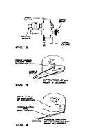
4.
Install sheave on Input shaft as close to reducer as
practical (See Fig 2) 5. Install motor and V-belt drive so belt
pull will approximately be at right angles to the center line
between driven and input shaft (See Fig 3). This will permit
tightening the V-belt drive with the torque arm.
6.
Install torque arm and adapter plates using the long
reducer bolts The bolts may be shifted to any of the holes on
the input end of the reducer .
7.
Install torque arm fulcrum on a rigid support so that the
torque arm will be approximately at right angles ( + 300) to the
center line through the driven shaft and the torque arm anchor
screw (See Fig 4) Make sure that there is sufficient take-up in
the turnbuckle for belt tension adjustment when using V-belt
drive.
LUBRICATION
Caution: Reducer is shipped without oil Add the proper
amount of oil before running.
Use a high grade petroleum base, rust and oxidation
inhibited (R & O) gear oil-see tables Follow instructions on
reducer nameplate, warning tags, and in the Installation
manual.
Under
average
Industrial
operating
conditions,
the
lubricant should be changed every 2500 hours of operation or
every 6 months, whichever occurs first Drain reducer and
flush with kerosene, clean magnetic drain plug and refill to
CAUTION
Extreme
pressure
(EP)
lubricants
are
not
recommended for average operating conditions.
proper level with new lubricant.
Caution: Too much oil will cause overheating and too
little will result in gear failure Check oil level regularly
Under extreme operating conditions, such as rapid rise
and fall of temperature, dust, dirt, chemical particles,
chemical fumes, or oil sump temperatures above 2000F.,
the oil should be changed every 1 to 3 months depending
on seventy of conditions.
WARNING
Do not use EP oils or oils containing slippery additives
such as graphite or molybdenum disulfide in the
reducer when backstop is used. These additives will
destroy sprag action.
(page 3-564)