TM 5-3895-374-24-1
Chapter 9
Troubleshooting
This chapter describes the most common troubleshooting procedures. It
describes.
•
troubleshooting module problems using the Communications LED
•
troubleshooting module problems using the module display
•
troubleshooting communications problems using the module display
•
troubleshooting function problems using tie module display
•
troubleshooting MSG Instruction error codes
•
troubleshooting processor faults using the module display
Troubleshooting Module
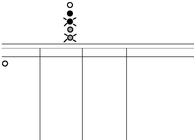
Refer to the following log to determine the status of the LED
Problems Using the
indicators:
Communications LED
Indicates the LED is OFF.
Indicates the LED is ILLUMINATED RED.
Indicates the LED is FLASHING RED.
Indicates the LED is ILLUMINATED GREEN.
Indicates the LED is FLASHING GREEN.
TROUBLESHOOTING CONSIDERATIONS
COMMUNICATIONS
INDICATOR
DESCRIPTION
PROBABLE CAUSES
RECOMMENDED ACTION
OFF
Module Does Not Power
Up
Bad Cable Connection
1. Verify proper connections on the
module
2. Verify proper connections to
processor or link coupler
3. Replace 1747-C10 Cable.
Power Supply Overloaded
Evaluate chassis backplane loading for
proper sizing of power supply
No Power to Link Coupler
if on DH-485 Network
If no processor is connected to link
coupler, provide 190mA ar 24 VDC to
screw terminals on link coupler
Defective Chassis Power
Supply
1. Cheek for proper power supply
connections
2. Check for proper power supply
voltage
3. Replace power supply
4. Disconnect module, call your Allen-
Bradley service representative.
page 3-395