TM 5-3895-374-24-1
Options
ALTIVAR 0,75 to 30 kW
Installation of the resistance
Supplied with the standardized resistance are: - a thermocontact and two clamping collars,
- two fixing brackets,
- mounting and connecting instructions
When installing, make sure that there is a free space of 50 mm minimum around the resistance
to ensure dissipation of the heat dissipated
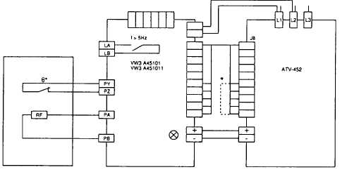
In order to avoid all accidental contact with the braking resistance (maximum DC voltage of 1000
between terminals, and a high temperature, which may reach 350° C when operating), the
installation of a protective cover is recommended Provide openings for circulation of the air
required for evacuating dissipated heat
Installation and connection of the optional module
Follow the procedure described in the service instruction delivered with the module
Safety precautions to take when wiring the resistance
- as the DC voltage at the resistance terminals can reach 1000 V at the start of braking, use
conductors with an insulation class of >1000V,
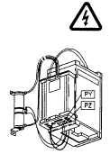
- ensure that the thermocontact is connected to the PY-PZ terminals of the braking module,
if this is not done, the state "contact open" will cause the controller to lock when switched on,
displaying the code 0hF
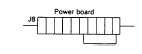
*If the braking option is not to be used, the connector delivered with the speed controller must be
plugged into J8, in order ro cancel the temperature control of the braking resistance
If the speed regulation is not to be used, do not connect the wire between the module and the J3
connector of the speed controller's control board
If the motor is fitted with a brake whose windings are accessible via terminals, connect the
contact of the low speed relay available at terminals LA-LB into the control sequence, contact
characteristics 220/240V - 50/60Hz - 2A
(page 3-219)