TM 5-3895-374-24-1
Options
For the ALTIVAR 0,75 to 30 kW, the VW3-A45101 and VW3-A451011 modules contain the
element making up the option, with a capacitor charge indicator on the front
For the ALTIVAR 37 to 90 kW, the power transistor is incorporated directly into the speed
controller the other elements making up the option are located on the VW3-A45201 D90 board
Characteristics
Maximum admissible current in the resistance is linked to
- the braking resistance value,
- the associated controller’s current limitation,
- the maximum power transistor current
• 50 A for VW3-A45101 module,
• 75 A for VW3-A45101 1 module,
• 100 A for ATV-452D37 (N) and D55 (N) speed controllers,
• 200 A for ATV-452D55S, ATV-452D75 (N) and D90 (N) speed controllers
Protection
The power transistor is protected against short-circuits at the braking resistance terminals
Available braking torque
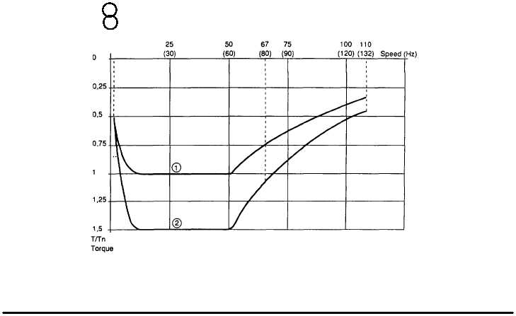
Typical braking curves -
1 Permanent braking torque (dnving load)
2 Maximum transient braking torque
When frequency is 10Hz,braking torque decreases rapidly.
Slip compensation does not exist with hypersynchronous braking.
(page 3-214)


