TM 5-3895-374-24-1
Recommendations for use
of the motor/speed controller combination
Electrical characteristics
Reference
I
L
Losses
Screw terminal connections
A
mH
W
.17
Inputs / Outputs
VZ1-LO05UM50T
5
5
24
M10/10P
6 x M4/6
VZ1-L015UM17T
15
1,7
44
M1b/10P
6 x M10110
VZ1-L030U800T
30
0,8
58
Mio/10P
6x M16/12
VZ1-L040U600T
40
0,6
67
M010/P
6xM16/12
VZ1-L070U350T
70
0,35
80
M10/10P
6 x M35/16
Bar terminations
VZ1-L150U170T
150
0,17
160
M8 screws
6 x 20 x 5
VZ1-L250U100T
250
0,1
200
M8 screws
6 x 30 x 5
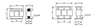
Dimensions - Weights
VZ1-L005UM50T to L070U350T
VZ1-L150U170T and L250U100T
Reference
a
b
c
c1
G
H
0
Weight (kg)
VZ1-L005UM50T
100
130
60
52
40/60
40
5
1,000
VZ1-L015UM17T
120
150
80
75
60/80,5
52
6
2,100
VZ1-LO30U800T
150
180
120
100
75/106,5
76
7
4,100
VZ1-L040U600T
180
215
130
100
85/122
76
7
5,100
VZ1-L070U350T
180
215
150
130
85/122
97
7
8,000
VZ1-L15OU17OT
270
240
170
140
105/181
96
11,5
14,900
VZ1-L250U100T
270
240
220
160
105/181
125
11,5
24,300
Installation precautions
Install the inductances vertically (as shown on the diagrams above), leaving sufficient
space to ensure the circulation of the air needed for cooling
When operation is prolonged, the temperature of the metal parts can exceed 100°C
(page 3-188)