TM 5-3895-368-14&P
Section III. - OPERATING INSTRUCTIONS
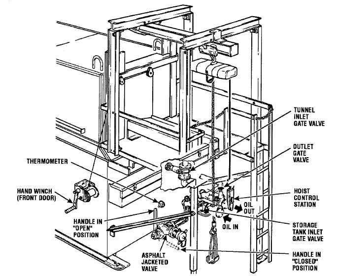
Figure 3-1. Controls and Instruments.
3-1.
Controls and Instruments.
a. General. Before beginning operation of the
asphalt melter unit, operators should become thoroughly
familiar with the location and function of all controls and
instruments. The following paragraphs describe each
control and instrument unique to the asphalt melter.
Consult operator instructions supplied with heat source
unit and asphalt distributor pump for identification of
controls on those units.
b. Thermometer. The asphalt material tempera-
ture gauge (Figure 3-1) is a direct, gauge reading, bi-
metal thermometer for monitoring the temperature of the
melted asphalt material in the storage tank. For most
efficient transfer of asphalt material, temperature should
be maintained at approximately 235°F. for 85-100
penetration asphalt cement.
c. Tunnel Inlet Gate Valve. The tunnel inlet gate
valve (Figure 3-1), located at the right side of the melter,
is an all iron, rising stem gate valve, with a forged steel
disc. This valve is used to regulate the flow of heat
transfer oil to the heat coils of the de-drumming tunnel.
During dedrumming operations, this valve is normally in
the full open position. When de-drumming has been
completed, this valve is closed, directing all heat transfer
oil to the heat coils in the bottom of the storage tank.
d. Storage Tank Inlet Gate Valve. The storage
tank inlet gate valve (Figure 3-1), located on the lower
piping connection to the storage tank, is identical in
construction to the tunnel inlet gate valve. This valve
regulates the flow of heat transfer oil to the heating coils
in the storage tank. During de-drumming operations, this
valve must be used in conjunction with the tunnel inlet
gate valve to divide the flow of heat transfer oil between
3-1