TM 5-3895-374-24-2
FLAME SAFEGUARD
Test for Incandescent Refractory Hold-In with Photocell Detector
Type 45CM 1 Photocell Scanners are actuated by light energy. To assure that the flame failure response
time is not extended by radiation from incandescent refractory, the following test is recommended
1.
Operate the burner, following the burner manufacturer’s instructions, until the refractory is at
maximum operating temperature.
2.
Turn off the main fuel supply manually.
3.
Observe the display flame signal which must drop below 10 within 4 seconds.
4.
If the flame failure response time exceed 4 seconds, reduce the amount of light at the Photocell with a
screen, an orifice, or a filter lens, until the normal flame failure response is obtained.
INSTALLATION - 69ND1 FLAME ROD
The 69ND1 flame rod proves a gas pilot flame and/or main gas flame. It is a spark plug type unit
consisting of 1/2" NPT mount, a KANTHAL flame rod, a glazed porcelain insulating rod holder and a spark
plug connector for making electrical connections. The 69ND1 is available in 12," 18" or 24" lengths.
The flame rod may be located to monitor only the gas pilot flame or both the gas pilot and main gas
flames. It is mounted on a 1/2" NPT coupling.
The following instructions should be observed:
1.
Keep flame rod as short as possible.
2.
Keep flame rod at least 1/2" from any refractory.
3.
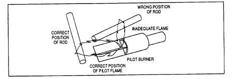
Flame rod should enter the pilot flame from the side so as to safely prove an adequate pilot flame
under all draft conditions.
4.
If the flame is nonluminous (air and gas mixed before burning), the electrode tip should extend at least
1/2" into the flame, but not more than half-way through.
5.
If the flame is partly luminous, the electrode tip should extend only to the edge of the flame. It is not
necessary to maintain absolutely uninterrupted contact with the flame.
6.
It is preferable to angle the rod downward to minimize the effect of sagging and to prevent it from
coming in contact with any object.
7.
An adequate grounding surface for the flame must be provided. The grounding surface in actual
contact with the flame must be at least four times greater than the area of the portion of the flame rod
in contact with the flame. It is essential to adjust the flame rod and ground area ratio to provide a
maximum signal reading.
Note: Interference from the ignition spark can alter the true signal reading by adding to, or subtracting from it. This trend
sometimes may be reversed by interchanging the primary wires (line voltage) to the ignition transformer. This interference
can also be reduced by the addition of grounded shielding between the flame rod and ignition spark.
(page 3 - 1061)