TM 5-3895-374-24-2
FLAME SAFEGUARD
Scanner Wiring
Care should be taken to see that ignitor cables and scanner cables are routed away from one another on
all installations. These cables, when crossed or run together, may interfere with the proper operation of
the flame safeguard control.
If you are experiencing erratic operation or inappropriate characters on the display during the trial for
ignition period, the cause is likely to be ignitor noise. Check for worn ignitor cable insulation, broken or cut
insulation or loose connectors at the electrode and transformers.
INSTALLATION - UV SCANNERS
CAUTION: The UV1, UV2, UV8, and 45UV3 ultra-violet name scanners and associated amplifier
modules are non-self-checking UV systems and should be applied only to burners that cycle often
(e.g. a minimum of once per 12 hours) in order for the safety checking circuit to be exercised.
(see Operation). If component checking is required during burner operation for constantly tired
burners, utilize the self-checking ultra-violet name scanners (45UV5) and associated amplifier
module (EUVS4).
Where possible, obtain the burner manufacturer’s instructions for mounting the scanner. This information
is available for most standard burners. The scanner mounting should comply with the following general
instructions:
1.
Position the UV1, UV2 scanner within 18 inches of the flame to be monitored; the 45UV5 within 30
inches, closer if possible.
2.
Select a scanner location that will remain within the ambient temperature limits of the UV Scanner. If
cooling is required, use an insulating coupling (Fireye #35-9 for UV1, UV2 Scanners, 35-127-1 for
45UV5) to reduce conducted heat.
3.
The UV1, UV2,45UV5 Scanners are designed to seal off the sight pipe up to 1 PSI pressure. Higher
furnace pressures should be sealed off. To seal off positive furnace pressure up to 100 PSI for UV1
UV2 Scanners, install a quartz window coupling (#60-1257) For 45fUV5 Scanners, use #60-1100
coupling. Add cooling air to reduce the scanner sight pipe temperature.
4.
Install the scanner on a standard NPT pipe (UV1 1/2" UV2: 3/8", 45UV5: 1-) whose position is rigidly
fixed. If the scanner mounting pipe sights through the refractory, do not extend it more than halfway
through. Swivel flanges are available if desired (#60-302 for UV1 UV2 Scanners, #60-1664-3
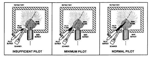
for45UV5). The sight pipe must permit an unobstructed view of the pilot and/or main flame, and both
pilot and main flames must completely cover the scanner field of view.
page 3 - 1057