TM 5-3895-374-24-2
FLAME SAFEGUARD
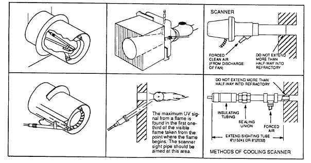
Note: Since oil and gas flames radiate more ultraviolet energy from the base of the flame than from further
out in the flame this fact should be taken into consideration when installing the scanner sight pipe.
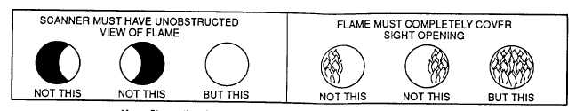
CAUTION: The scanner must not sight the ignition spark directly, or any part of the burner that
can reflect the spark back to the scanner. The scanner must not see a pilot flame that is too small
to reliably ignite the main flame.
5.
Smoke or unburned combustion gases absorb ultraviolet energy. On installations with negative
pressure combustion chambers, a small hole drilled in the UV 1, UV2 sight pipe will assist in keeping
the pipe clean and free from smoke. The 45UV5 has a 3/8” plug in the mounting flange that can be
removed. For positive pressure furnaces, provide clean air to pressurize the sight pipe, if necessary.
6. Two UV or UV2 Scanners may be installed on the burner if it is necessary to view two areas to obtain
reliable detection of the flame. They should be wired in parallel. Only one repetitive self- checking
45UV5 Scanner may be installed on a burner.
7. To increase scanner sensitivity with UV1, UV2 Scanners, a quartz lens permits location of the scanner
at twice the normal distance. Use 1/2" x 1 1/2" pipe nipple between UV 1 Scanner and the coupling.
Use 3/8" pipe nipple and a 1/2" x 3/8" bushing on UV2 installations.
8. Request the assistance of any Fireye field office for recommendations of a proper scanner installation
on a non-standard application.
Typical Scanner Installations
page 3 - 1058