TM 5-3895-374-24-2
KITO TF SERIES PLAIN -AND GEARED
TROLLEY
Before Use
The KITO manual trolley can be adjusted in increments of 1/8" by simply inserting or removing adjust-
ing spacers, to fit a variety of beam width. No additional spacers required.
1. Connection to electric or manual chain hoist.
Connection of KITO trolley to an electric or manual chain hoist is made directly by hanging the top
hook to the suspension shaft.
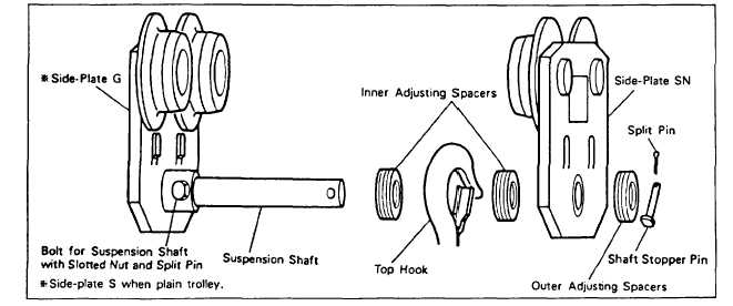
2. Assembly of trolley
1)
Insert the suspension shaft into the side-plate G (when geared trolley) or side-plate S (when plain
trolley), and fix it with the bolt for suspension shaft.
2)
Insert the suspension shaft into the inner adjusting spacers and the top hook, referring to Fig. 1 and
Table 1.
3)
Insert the suspension shaft into the side-plate SN and insert the outer spare adjusting spacers outside
of the side-plate SN, and insert the shaft stopper pin into the suspension shaft and also insert split
pin into the shaft stopper pin. Bend securely both branches of the split pin after insertion.
4)
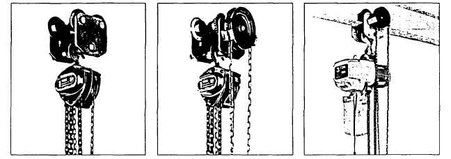
When connecting a geared trolley to an electric chain hoist, take care so that the hand chain may be
on the opposite side of the power supply cable. (Refer to Photo.) Fig. 1
(page 3 - 875)