TM 5-3895-374-24-1
GP467FB
NOTE
The thermocouple lead wires should be run separately from all other wiring. If run with other cables, stray
currents could cause false readings.
7.
Mount the flame scanner(s) on the burner and wire the unit(s) into the panel
NOTE
The scanner cable(s) from the burner to the panel must be run separately from all other cables. If run with
other cables, stray currents could cause false scanner readings and nuisance shutdowns
8.
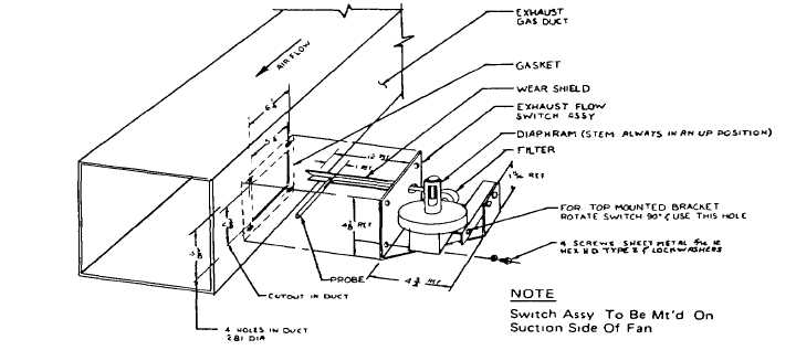
Mount the exhaust fan flow switch in the dryer exhaust duct as shown in figure 3.
Fig 3-Drawing showing the installation of the exhaust fan flow switch.
9.
Wire the exhaust flow switch to the appropriate terminals. The exhaust flow switch is an Interlock which requires the
exhauster to be operating prior to ignition of the burner.
10. If gas is used to fire the burner, wire the automatic valves and switches in the gas supply line to the appropriate
terminals On oil and LP fired systems, these units are normally prewired at the factory.
11. Wire the control cable to the control panel. Wire the other end of the control cable to the burner junction box, (if
applicable).
(PAGE 3-11)